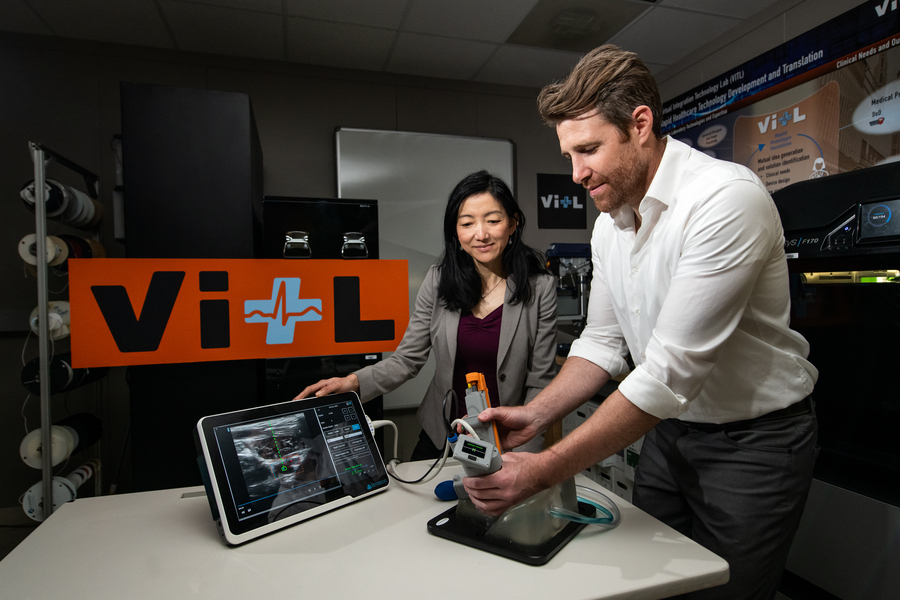
Matt Johnson (right) and Laura Brattain (left) test a new medical device on an artificial model of human tissue and blood vessels. The device helps users to insert a needle and guidewire quickly and accurately into a vessel, a crucial first step to halting rapid blood loss. Photo: Nicole Fandel.
By Anne McGovern | MIT Lincoln Laboratory
After a traumatic accident, there is a small window of time when medical professionals can apply lifesaving treatment to victims with severe internal bleeding. Delivering this type of care is complex, and key interventions require inserting a needle and catheter into a central blood vessel, through which fluids, medications, or other aids can be given. First responders, such as ambulance emergency medical technicians, are not trained to perform this procedure, so treatment can only be given after the victim is transported to a hospital. In some instances, by the time the victim arrives to receive care, it may already be too late.
A team of researchers at MIT Lincoln Laboratory, led by Laura Brattain and Brian Telfer from the Human Health and Performance Systems Group, together with physicians from the Center for Ultrasound Research and Translation (CURT) at Massachusetts General Hospital, led by Anthony Samir, have developed a solution to this problem. The Artificial Intelligence–Guided Ultrasound Intervention Device (AI-GUIDE) is a handheld platform technology that has the potential to help personnel with simple training to quickly install a catheter into a common femoral vessel, enabling rapid treatment at the point of injury.
“Simplistically, it’s like a highly intelligent stud-finder married to a precision nail gun.” says Matt Johnson, a research team member from the laboratory’s Human Health and Performance Systems Group.
AI-GUIDE is a platform device made of custom-built algorithms and integrated robotics that could pair with most commercial portable ultrasound devices. To operate AI-GUIDE, a user first places it on the patient’s body, near where the thigh meets the abdomen. A simple targeting display guides the user to the correct location and then instructs them to pull a trigger, which precisely inserts the needle into the vessel. The device verifies that the needle has penetrated the blood vessel, and then prompts the user to advance an integrated guidewire, a thin wire inserted into the body to guide a larger instrument, such as a catheter, into a vessel. The user then manually advances a catheter. Once the catheter is securely in the blood vessel, the device withdraws the needle and the user can remove the device.
With the catheter safely inside the vessel, responders can then deliver fluid, medicine, or other interventions.
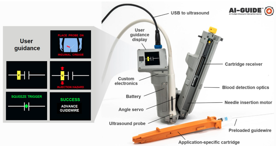
AI-GUIDE automates nearly every step of the process to locate and insert a needle, guidewire, and catheter into a blood vessel to facilitate lifesaving treatment. The version of the device shown here is optimized to locate the femoral blood vessels, which are in the upper thigh. Image courtesy of the researchers.
As easy as pressing a button
The Lincoln Laboratory team developed the AI in the device by leveraging technology used for real-time object detection in images.
“Using transfer learning, we trained the algorithms on a large dataset of ultrasound scans acquired by our clinical collaborators at MGH,” says Lars Gjesteby, a member of the laboratory’s research team. “The images contain key landmarks of the vascular anatomy, including the common femoral artery and vein.”
These algorithms interpret the visual data coming in from the ultrasound that is paired with AI-GUIDE and then indicate the correct blood vessel location to the user on the display.
“The beauty of the on-device display is that the user never needs to interpret, or even see, the ultrasound imagery,” says Mohit Joshi, the team member who designed the display. “They are simply directed to move the device until a rectangle, representing the target vessel, is in the center of the screen.”
For the user, the device may seem as easy to use as pressing a button to advance a needle, but to ensure rapid and reliable success, a lot is happening behind the scenes. For example, when a patient has lost a large volume of blood and becomes hypotensive, veins that would typically be round and full of blood become flat. When the needle tip reaches the center of the vein, the wall of the vein is likely to “tent” inward, rather than being punctured by the needle. As a result, though the needle was injected to the proper location, it fails to enter the vessel.
To ensure that the needle reliably punctures the vessel, the team engineered the device to be able to check its own work.
“When AI-GUIDE injects the needle toward the center of the vessel, it searches for the presence of blood by creating suction,” says Josh Werblin, the program’s mechanical engineer. “Optics in the device’s handle trigger when blood is present, indicating that the insertion was successful.” This technique is part of why AI-GUIDE has shown very high injection success rates, even in hypotensive scenarios where veins are likely to tent.
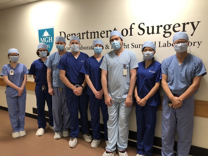
Lincoln Laboratory researchers and physicians from the Massachusetts General Hospital Center for Ultrasound Research and Translation collaborated to build the AI-GUIDE system. Photo courtesy of Massachusetts General Hospital.
Recently, the team published a paper in the journal Biosensors that reports on AI-GUIDE’s needle insertion success rates. Users with medical experience ranging from zero to greater than 15 years tested AI-GUIDE on an artificial model of human tissue and blood vessels and one expert user tested it on a series of live, sedated pigs. The team reported that after only two minutes of verbal training, all users of the device on the artificial human tissue were successful in placing a needle, with all but one completing the task in less than one minute. The expert user was also successful in quickly placing both the needle and the integrated guidewire and catheter in about a minute. The needle insertion speed and accuracy were comparable to that of experienced clinicians operating in hospital environments on human patients.
Theodore Pierce, a radiologist and collaborator from MGH, says AI-GUIDE’s design, which makes it stable and easy to use, directly translates to low training requirements and effective performance. “AI-GUIDE has the potential to be faster, more precise, safer, and require less training than current manual image-guided needle placement procedures,” he says. “The modular design also permits easy adaptation to a variety of clinical scenarios beyond vascular access, including minimally invasive surgery, image-guided biopsy, and imaging-directed cancer therapy.”
In 2021, the team received an R&D 100 Award for AI-GUIDE, recognizing it among the year’s most innovative new technologies available for license or on the market.
What’s next?
Right now, the team is continuing to test the device and work on fully automating every step of its operation. In particular, they want to automate the guidewire and catheter insertion steps to further reduce risk of user error or potential for infection.
“Retraction of the needle after catheter placement reduces the chance of an inadvertent needle injury, a serious complication in practice which can result in the transmission of diseases such as HIV and hepatitis,” says Pierce. “We hope that a reduction in manual manipulation of procedural components, resulting from complete needle, guidewire, and catheter integration, will reduce the risk of central line infection.”
AI-GUIDE was built and tested within Lincoln Laboratory’s new Virtual Integration Technology Lab (VITL). VITL was built in order to bring a medical device prototyping capability to the laboratory.
“Our vision is to rapidly prototype intelligent medical devices that integrate AI, sensing — particularly portable ultrasound — and miniature robotics to address critical unmet needs for both military and civilian care,” says Laura Brattain, who is the AI-GUIDE project co-lead and also holds a visiting scientist position at MGH. “In working closely with our clinical collaborators, we aim to develop capabilities that can be quickly translated to the clinical setting. We expect that VITL’s role will continue to grow.”
AutonomUS, a startup company founded by AI-GUIDE’s MGH co-inventors, recently secured an option for the intellectual property rights for the device. AutonomUS is actively seeking investors and strategic partners.
“We see the AI-GUIDE platform technology becoming ubiquitous throughout the health-care system,” says Johnson, “enabling faster and more accurate treatment by users with a broad range of expertise, for both pre-hospital emergency interventions and routine image-guided procedures.”
This work was supported by the U.S. Army Combat Casualty Care Research Program and Joint Program Committee – 6. Nancy DeLosa, Forrest Kuhlmann, Jay Gupta, Brian Telfer, David Maurer, Wes Hill, Andres Chamorro, and Allison Cheng provided technical contributions, and Arinc Ozturk, Xiaohong Wang, and Qian Li provided guidance on clinical use.