Page 429 of 430
1 427 428 429 430

Japan’s World Robot Summit posts challenges for teams

Japan is holding a huge robot celebration in 2018 in Tokyo and 2020 in Aichi, Fukushima, hosted by the Ministry of Economy, Trade and industry (METI) and the New Energy Industrial Technology Development Organization (NEDO). This is a commercial robotics Expo and a series of robotics Challenges with the goal of bringing together experts from around the world to advance human focused robotics.

The World Robot Summit website was just launched on March 2, 2017. The results of tenders for standard robot platforms for the competitions are being announced soon and the first trials for competition teams should happen in summer 2017.

There are a total of 8 challenges that fall into 4 categories: Industrial Robotics, Service Robotics, Disaster Robotics and Junior.

Industrial: Assembly Challenge – quick and accurate assembly of model products containing technical components require in assembling industrial products and other goods.

Service: Partner Robot Challenge – setting tasks equivalent to housework and making robots that complete such tasks – utilizing a standard robot platform.

Service: Automation of Retail Work Challenge – making robots to complete tasks eg. shelf stocking and replenishment multiple types of products such as foods, interaction between customers and staffs and cleaning restrooms.

Disaster: Plant Disaster Prevention Challenge – inspecting or maintaining infrastructures based on set standards eg. opening/closing valves and exchanging consumable supplies and searching for disaster victims.

Disaster: Tunnel Disaster Response and Recovery Challenge – collecting information and providing emergency response in case of a tunnel disaster eg. saving lives and removing vehicles from tunnels.

Disaster: Standard Disaster Robotics Challenge – assessing standard performance levels eg. mobility, sensing, information collection, wireless communication, remote control on-site deployment and durability, etc. require in disaster prevention and response.

Junior (aged 19 or younger): School Robot Challenge – making robots to complete tasks that might be useful in a school environment – utilizing a standard robot platform.

Junior (aged 19 or younger): Home Robot Challenge – setting tasks equivalent to housework and making robots that complete such tasks.

The World Robot Summit, Challenge, Expo and Symposiums are looking for potential teams and major sponsors. 

For more information, you can email: Wrs@keieiken.co.jp

Robots Podcast #230: bots_alive, with Bradley Knox


In this episode, Audrow Nash interviews Bradley Knox, founder of bots_alive. Knox speaks about an add-on to a Hexbug, a six-legged robotic toy, that makes the bot behave more like a character. They discuss the novel way Knox uses machine learning to create a sense character. They also discuss the limitation of technology to emulate living creatures, and how the bots_alive robot was built within these limitations.


Brad Knox

Dr. Bradley Knox is the founder of bots_alive. He researched human-robot interaction, interactive machine learning, and artificial intelligence at the MIT Media Lab and at UT Austin. At MIT, he designed and taught Interactive Machine Learning. He has won two best paper awards at major robotics and AI conferences, was awarded best dissertation from UT Austin’s Computer Science Department, and was named to IEEE’s AI’s 10 to Watch in 2013.


Links

Bosch and Nvidia partner to develop AI for self-driving cars

Amongst all the activity in autonomously driven vehicle joint ventures, new R&D facilities, strategic acquisitions (such as Mobileye being acquired by Intel) and booming startup fundings, two big players in the industry, NVIDIA and Bosch, are partnering to develop an AI self-driving car supercomputer.

Bosch CEO Dr Volkmar Denner announced the partnership during his keynote address at Bosch Connected World, in Berlin.

“Automated driving makes roads safer, and artificial intelligence is the key to making that happen,” said Denner. “We are making the car smart. We are teaching the car how to maneuver through road traffic by itself.”

The Bosch AI car computer will use NVIDIA AI PX technology, the upcoming AI car superchip, advertised as the world’s first single-chip processor designed to achieve Level-4 autonomous driving (see ADAS chart). The unprecedented level of performance is necessary to handle the massive amount of computation required for the various tasks self-driving vehicles must perform which include running deep neural nets to sense surroundings, understanding the 3D environment, localizing themselves on an HD map, predicting the behavior and position of other objects, as well as computing car dynamics and a safe path forward.

Source: Frost & Sullivan;VDS Automotive SYS Konferenz 2014/


Essentially, the NVIDIA platform enables vehicles to be trained on the complexities of driving, operated autonomously and updated over the air with new features and capabilities. And Bosch, which is the one of the world’s largest auto parts makers, has the Tier 1 credentials to mass-produce this AI-enabled supercomputer for a good portion of the auto industry.

“Self-driving cars is a challenge that can finally be solved with recent breakthroughs in deep learning and artificial intelligence,” said Jen-Hsun Huang, founder and CEO, NVIDIA. “Using DRIVE PX AI car computer, Bosch will build automotive-grade systems for the mass production of autonomous cars. Together we will realize a future where autonomous vehicles make mobility safe and accessible to all.”

Nvidia is also partnering with automakers Audi and Mercedes-Benz.

Bottom line:

“This is the kind of strategic tie-up that lets both partners do what they do best – Nvidia can focus on developing the core AI supercomputing tech, and Bosch can provide relationships and sales operations that offer true scale and reach,” says Darrell Etherington for TechCrunch.

Security for multirobot systems

Researchers including MIT professor Daniela Rus (left) and research scientist Stephanie Gil (right) have developed a technique for preventing malicious hackers from commandeering robot teams’ communication networks. To verify the theoretical predictions, the researchers implemented their system using a battery of distributed Wi-Fi transmitters and an autonomous helicopter. Image: M. Scott Brauer.

Distributed planning, communication, and control algorithms for autonomous robots make up a major area of research in computer science. But in the literature on multirobot systems, security has gotten relatively short shrift.

In the latest issue of the journal Autonomous Robots, researchers from MIT’s Computer Science and Artificial Intelligence Laboratory and their colleagues present a new technique for preventing malicious hackers from commandeering robot teams’ communication networks. The technique could provide an added layer of security in systems that encrypt communications, or an alternative in circumstances in which encryption is impractical.

“The robotics community has focused on making multirobot systems autonomous and increasingly more capable by developing the science of autonomy. In some sense we have not done enough about systems-level issues like cybersecurity and privacy,” says Daniela Rus, an Andrew and Erna Viterbi Professor of Electrical Engineering and Computer Science at MIT and senior author on the new paper.

“But when we deploy multirobot systems in real applications, we expose them to all the issues that current computer systems are exposed to,” she adds. “If you take over a computer system, you can make it release private data — and you can do a lot of other bad things. A cybersecurity attack on a robot has all the perils of attacks on computer systems, plus the robot could be controlled to take potentially damaging action in the physical world. So in some sense there is even more urgency that we think about this problem.”

Identity theft

Most planning algorithms in multirobot systems rely on some kind of voting procedure to determine a course of action. Each robot makes a recommendation based on its own limited, local observations, and the recommendations are aggregated to yield a final decision.

A natural way for a hacker to infiltrate a multirobot system would be to impersonate a large number of robots on the network and cast enough spurious votes to tip the collective decision, a technique called “spoofing.” The researchers’ new system analyzes the distinctive ways in which robots’ wireless transmissions interact with the environment, to assign each of them its own radio “fingerprint.” If the system identifies multiple votes as coming from the same transmitter, it can discount them as probably fraudulent.

“There are two ways to think of it,” says Stephanie Gil, a research scientist in Rus’ Distributed Robotics Lab and a co-author on the new paper. “In some cases cryptography is too difficult to implement in a decentralized form. Perhaps you just don’t have that central key authority that you can secure, and you have agents continually entering or exiting the network, so that a key-passing scheme becomes much more challenging to implement. In that case, we can still provide protection.

“And in case you can implement a cryptographic scheme, then if one of the agents with the key gets compromised, we can still provide  protection by mitigating and even quantifying the maximum amount of damage that can be done by the adversary.”

Hold your ground

In their paper, the researchers consider a problem known as “coverage,” in which robots position themselves to distribute some service across a geographic area — communication links, monitoring, or the like. In this case, each robot’s “vote” is simply its report of its position, which the other robots use to determine their own.

The paper includes a theoretical analysis that compares the results of a common coverage algorithm under normal circumstances and the results produced when the new system is actively thwarting a spoofing attack. Even when 75 percent of the robots in the system have been infiltrated by such an attack, the robots’ positions are within 3 centimeters of what they should be. To verify the theoretical predictions, the researchers also implemented their system using a battery of distributed Wi-Fi transmitters and an autonomous helicopter.

“This generalizes naturally to other types of algorithms beyond coverage,” Rus says.

The new system grew out of an earlier project involving Rus, Gil, Dina Katabi — who is the other Andrew and Erna Viterbi Professor of Electrical Engineering and Computer Science at MIT — and Swarun Kumar, who earned master’s and doctoral degrees at MIT before moving to Carnegie Mellon University. That project sought to use Wi-Fi signals to determine transmitters’ locations and to repair ad hoc communication networks. On the new paper, the same quartet of researchers is joined by MIT Lincoln Laboratory’s Mark Mazumder.

Typically, radio-based location determination requires an array of receiving antennas. A radio signal traveling through the air reaches each of the antennas at a slightly different time, a difference that shows up in the phase of the received signals, or the alignment of the crests and troughs of their electromagnetic waves. From this phase information, it’s possible to determine the direction from which the signal arrived.

Space vs. time

A bank of antennas, however, is too bulky for an autonomous helicopter to ferry around. The MIT researchers found a way to make accurate location measurements using only two antennas, spaced about 8 inches apart. Those antennas must move through space in order to simulate measurements from multiple antennas. That’s a requirement that autonomous robots meet easily. In the experiments reported in the new paper, for instance, the autonomous helicopter hovered in place and rotated around its axis in order to make its measurements.

When a Wi-Fi transmitter broadcasts a signal, some of it travels in a direct path toward the receiver, but much of it bounces off of obstacles in the environment, arriving at the receiver from different directions. For location determination, that’s a problem, but for radio fingerprinting, it’s an advantage: The different energies of signals arriving from different directions give each transmitter a distinctive profile.

There’s still some room for error in the receiver’s measurements, however, so the researchers’ new system doesn’t completely ignore probably fraudulent transmissions. Instead, it discounts them in proportion to its certainty that they have the same source. The new paper’s theoretical analysis shows that, for a range of reasonable assumptions about measurement ambiguities, the system will thwart spoofing attacks without unduly punishing valid transmissions that happen to have similar fingerprints.

“The work has important implications, as many systems of this type are on the horizon — networked autonomous driving cars, Amazon delivery drones, et cetera,” says David Hsu, a professor of computer science at the National University of Singapore. “Security would be a major issue for such systems, even more so than today’s networked computers. This solution is creative and departs completely from traditional defense mechanisms.”

If you enjoyed this article from CSAIL, you might also be interested in:

See all the latest robotics news on Robohub, or sign up for our weekly newsletter.

Collaborating machines and avoiding soil compression

Image: Swarmfarm

Soil compression can be a serious problem, but it isn’t always, or in all ways, a bad thing. For example, impressions made by hoofed animals, so long as they only cover a minor fraction of the soil surface, create spaces in which water can accumulate and help it percolate into the soil more effectively, avoiding erosion runoff.

The linear depressions made by wheels rolling across the surface are more problematic because they create channels that can accelerate the concentration of what would otherwise be evenly distributed rainfall, turning it into a destructive force. This is far less serious when those wheels follow the contour of the land rather than running up and down slopes.

Taking this one step further, if it is possible for wheeled machines to always follow the same tracks, the compression is localized and the majority of the land area remains unaffected. If those tracks are filled with some material though which water can percolate but which impedes the accumulation of energy in downhill flows, the damage is limited to the sacrifice of the portion of the overall land area dedicated to those tracks and the creation of compression zones beneath them, which may result in boggy conditions on the uphill sides of the tracks, which may or may not be a bad thing, depending on what one is trying to grow there.

Source: vinbot.eu

(I should note at this point that such tracks, when they run on the contour, are reminiscent of the ‘swales’ used in permaculture and regenerative agriculture.)

Tractors with GPS guidance are capable of running their wheels over the same tracks with each pass, but the need for traction, so they can apply towing force to implements running through the soil, means that those tracks will constitute a significant percentage of the overall area. Machines, such as dedicated sprayers, with narrower wheels that can be spread more widely apart, create tracks which occupy far less of the total land area, but they are not built for traction, and using them in place of tractors for all field operations would require a very different approach to farming.

It is possible to get away from machine-caused soil compression altogether, using either aerial machines (drones) or machines which are supported by or suspended from fixed structures, like posts or rails.

Small drones are much like hummingbirds in that they create little disturbance, but they are also limited in the types of operations they can perform by their inability to carry much weight or exert significant force. They’re fine for pollination but you wouldn’t be able to use them to uproot weeds with tenacious roots or to harvest watermelons or pumpkins.

On the other hand, fixed structures and the machines that are supported by or suspended from them have a significant up-front cost. In the case of equipment suspended from beams or gantries spanning between rails and supported from wheeled trucks which are themselves supported by rails, there is a tradeoff between the spacing of the rails and the strength/stiffness required in the gantry. Center-pivot arrangements also have such a tradeoff, but they use a central pivot in place of one rail (or wheel track), and it’s common for them to have several points of support spaced along the beam, requiring several concentric rails or wheel tracks.

Strictly speaking, there’s no particular advantage in having rail-based systems follow the contour of the land since they leave no tracks at all. Center-pivot systems using wheels that run directly on the soil rather than rail are best used on nearly flat ground since their round tracks necessarily run downhill over part of their circumference. In any rail-based system, the “rail” might be part of the mobile unit rather than part of the fixed infrastructure, drawing support from posts spaced closely enough that there were always at least two beneath it. However, this would preclude using trough-shaped rails to deliver water for irrigation.

Since the time of expensive machines is precious, it’s best to avoid burdening them with operations that can be handled by small, inexpensive drones, and the ideal arrangement is probably a combination of small drones, a smaller number of larger drones with some carrying capacity, light on-ground devices that put little pressure on the soil, and more substantial machines supported or suspended from fixed infrastructure, whether rail, center-pivot, or something else. Livestock (chickens, for example), outfitted with light wearable devices, might also be part of the mix.

The small drones, being more numerous, will be the best source of raw data, which can be used to optimize the operation of the larger drones, on-ground devices, and the machines mounted on fixed infrastructure, although too much centralized control would not be efficient. Each device should be capable of continuing to do useful work even when it loses network connection, and peer-to-peer connections will be more appropriate than running everything through a central hub in some circumstances.

Bonirob, an agricultural robot. Source: Bosch


This is essentially a problem in complex swarm engineering, complex because of the variety of devices involved. Solving it in a way that creates a multi-device platform capable of following rules, carrying out plans, and recognizing anomalous conditions is the all-important first step in enabling the kind of robotics that can then go one to enable regenerative practices in farming (and land management in general).

If you enjoyed this article, you may also want to read:

See all the latest robotics news on Robohub, or sign up for our weekly newsletter.


Envisioning the future of robotics

Image: Ryan Etter

Robotics is said to be the next technological revolution. Many seem to agree that robots will have a tremendous impact over the following years, and some are heavily betting on it. Companies are investing billions buying other companies, and public authorities are discussing legal frameworks to enable a coherent growth of robotics.

Understanding where the field of robotics is heading is more than mere guesswork. While much public concern focuses on the potential societal issues that will arise with the advent of robots, in this article, we present a review of some of the most relevant milestones that happened in robotics over the last decades. We also offer our insights on feasible technologies we might expect in the near future.

Copyright © Acutronic Robotics 2017. All Rights Reserved.

Pre-robots and first manipulators

What’s the origin of robots? To figure it out we’ll need to go back quite a few decades to when different conflicts motivated the technological growth that eventually enabled companies to build the first digitally controlled mechanical arms. One of the first and well documented robots was UNIMATE (considered by many the first industrial robot): a programmable machine funded by General Motors, used to create a production line with only robots. UNIMATE helped improve industrial production at the time. This motivated other companies and research centers to actively dedicate resources to robotics, which boosted growth in the field.

Sensorized robots

Sensors were not typically included in robots until the 70’s. Starting in1968, a second generation of robots emerged that integrated sensors. These robots were able to react to their environment and offer responses that met varying scenarios.

Relevant investments were observed during this period. Industrial players worldwide were attracted by the advantage that robots promised.

Worldwide industrial robots:  Era of the robots

Many consider that the Era of Robots started in 1980. Billions of dollars were invested by companies all around to world to automate basic tasks in their assembly lines. Sales of industrial robots grew 80% above the previous years’.

Key technologies appeared within these years: General internet access was extended in 1980; Ethernet became a standard in 1983 (IEEE 802.3); the Linux kernel was announced in 1991; and soon after that real-time patches started appearing on top of Linux.

The robots created between 1980 and 1999 belong to what we call the third generation of robots: robots that were re-programmable and included dedicated controllers. Robots populated many industrial sectors and were used for a wide variety of activities: painting, soldering, moving, assembling, etc.

By the end of the 90s, companies started thinking about robots beyond the industrial sphere. Several companies created promising concepts that would inspire future roboticists. Among the robots created within this period, we highlight two:

  1. The first LEGO Mindstorms kit (1998): a set consisting of 717 pieces including LEGO bricks, motors, gears, different sensors, and a RCX Brick with an embedded microprocessor to construct various robots using the exact same parts. The kit allowed the learning of  basic robotics principles. Creative projects have appeared over the years showing the potential of interchangeable hardware in robotics. Within a few years. the LEGO Mindstorms kit became the most successful project that involved robot part interchangeability.
  2. Sony’s AIBO (1999): the world’s first entertainment robot. Widely used for research and development, Sony offered robotics to everyone in the form of a $1,500 robot that included a distributed hardware and software architecture. The OPEN-R architecture involved the use of modular hardware components — e.g. appendages that can be easily removed and replaced to customize the shape and function of the robots — and modular software components that could be interchanged to modify their behavior and movement patterns. OPEN-R inspired future robotic frameworks, and minimized the need for programming individual movements or responses.

Integration effort was identified as one of the main issues within robotics, particularly related to industrial robots. A common infrastructure typically reduces the integration effort by facilitating an environment in which components can be connected and made to interoperate. Each of the infrastructure-supported components are optimized for such integration at their conception, and the infrastructure handles the integration effort. At that point, components could come from different manufacturers (yet when supported by a common infrastructure, they will interoperate).

Sony’s AIBO and LEGO’s Mindstorms kit were built upon this principle, and both represented common infrastructures. Even though they came from the consumer side of robotics, one could argue that their success was strongly related to the fact that both products made use of interchangeable hardware and software modules. The use of a common infrastructure proved to be one of the key advantages of these technologies, however those concepts were never translated to industrial environments. Instead, each manufacturer, in an attempt to dominate the market, started creating their own “robot programming languages”.

The dawn of smart robots

Starting from the year 2000, we observed a new generation of robot technologies. The so-called fourth generation of robots consisted of more intelligent robots that included advanced computers to reason and learn (to some extend at least), and more sophisticated sensors that helped controllers adapt themselves more effectively to different circumstances.

Among the technologies that appeared in this period, we highlight the Player Project (2000, formerly the Player/Stage Project), the Gazebo simulator (2004) and the Robot Operating System (2007). Moreover, relevant hardware platforms appeared during these years. Single Board Computers (SBCs), like the Raspberry Pi, enabled millions of users all around the world to create robots easily.

The boost of bio-inspired artificial intelligence

The increasing popularity of artificial intelligence, and particularly neural networks, became relevant in this period as well. While a lot of the important work on neural networks happened in the 80’s and in the 90’s, computers did not have enough computational power at the time. Datasets weren’t big enough to be useful in practical applications. As a result, neural networks practically disappeared in the first decade of the 21st century. However, starting from 2009 (speech recognition), neural networks gained popularity and started delivering good results in fields such as computer vision (2012) or machine translation (2014). Over the last few years, we’ve seen how these techniques have been translated to robotics for tasks such as robotic grasping. In the coming years, we expect to see these AI techniques having more and more impact in robotics.

What happened to industrial robots?

Relevant key technologies have also emerged from the industrial robotics landscape (e.g.: EtherCAT). However, except for the appearance of the first so-called collaborative robots, the progress within the field of industrial robotics has significantly slowed down when compared to previous decades. Several groups have identified this fact and written about it with conflicting opinions. Below, we summarize some of the most relevant points encountered while reviewing previous work:

  • The Industrial robot industry :  is it only a supplier industry?
    For some, the industrial robot industry is a supplier industry. It supplies components and systems to larger industries, like manufacturing. These groups argue that the manufacturing industry is dominated by the PLC, motion control and communication suppliers which, together with the big customers, are setting the standards. Industrial robots therefore need to adapt and speak factory languages (PROFINET, ETHERCAT, Modbus TCP, Ethernet/IP, CANOPEN, DEVICENET, etc.) which for each factory, might be different.
  • Lack of collaboration and standardized interfaces in industry
    To date, each industrial robot manufacturer’s business model is somehow about locking you into their system and controllers. Typically, one will encounter the following facts when working with an industrial robot: a) each robot company has its own proprietary programming language, b) programs can’t be ported from one robot company to the next one, c) communication protocols are different, d) logical, mechanical and electrical interfaces are not standardized across the industry. As a result, most robotic peripheral makers suffer from having to support many different protocols, which requires a lot of development time that reduces the functionality of the product.
  • Competing by obscuring vs opening new markets?
    The closed attitude of most industrial robot companies is typically justified by the existing competition. Such an attitude leads to a lack of understanding between different manufacturers. An interesting approach would be to have manufacturers agree on a common infrastructure. Such an infrastructure could define a set of electrical and logical interfaces (leaving the mechanical ones aside due to the variability of robots in different industries) that would allow industrial robot companies to produce robots and components that could interoperate, be exchanged and eventually enter into new markets. This would also lead to a competitive environment where manufacturers would need to demonstrate features, rather than the typical obscured environment where only some are allowed to participate.

The Hardware Robot Operating System (H-ROS)

For robots to enter new and different fields, it seems reasonable that they need to adapt to the environment itself. This fact was previously highlighted for the industrial robotics case, where robots had to be fluent with factory languages. One could argue the same for service robots (e.g. households robots that will need to adapt to dish washers, washing machines, media servers, etc.), medical robots and many other areas of robotics. Such reasoning lead to the creation of the Hardware Robot Operating System (H-ROS), a vendor-agnostic hardware and software infrastructure for the creation of robot components that interoperate and can be exchanged between robots. H-ROS builds on top of ROS, which is used to define a set of standardized logical interfaces that each physical robot component must meet if compliant with H-ROS.

H-ROS facilitates a fast way of building robots, choosing the best component for each use-case from a common robot marketplace. It complies with different environments (industrial, professional, medical, …) where variables such as time constraints are critical. Building or extending robots is simplified to the point of placing H-ROS compliant components together. The user simply needs to program the cognition part (i.e. brain) of the robot and develop their own use-cases, all without facing the complexity of integrating different technologies and hardware interfaces.

The future ahead

With latest AI results being translated to robotics, and recent investments in the field, there’s a high anticipation for the near future of robotics.

As nicely introduced by Melonee Wise in a recent interview, there’s still not that many things you can do with a $1000-5000 BOM robot (which is what most people would pay on an individual basis for a robot). Hardware is still a limiting factor, and our team strongly believes that a common infrastructure, such as H-ROS, will facilitate an environment where robot hardware and software can evolve.

The list presented below summarizes, according to our judgement, some of the most technically feasible future robotic technologies to appear.

Acknowledgments

This review was funded and supported by Acutronic Robotics, a firm focused on the development of next-generation robot solutions for a range of clients.

The authors would also like to thank the Erle Robotics and the Acutronic groups for their support and help.

References

  • [1] Gates, B. ”A robot in every home,” Scientific American, 296(1), 2007, pp. 58–65. (link)
  • [2] Trikha, B. “ A Journey from floppy disk to cloud storage,” in International Journal on Computer Science and Engineering,Vol. 2, 2010, pp.1449–1452. (link)
  • [3] Copeland, B. J. “Colossus: its origins and originators,” in IEEE Annals of the History of Computing, Vol. 26, 2004, pp. 38–45. (link)
  • [4] Bondyopadhyay, P. K. “In the beginning [junction transistor],” in Proceedings of the IEEE, Vol. 86, 1998, pp.63–77. (link)
  • [5] Bryson, A. E. “Optimal control-1950 to 1985,” in IEEE Control Systems, Vol. 16, 1996, pp.26–33. (link)
  • [6] Middleditch, A. E. “Survey of numerical controller technology,” in Production Automation Project, University of Rochester, 1973. (link)
  • [7] Acal, A. P., & Lobera, A. S. “Virtual reality simulation applied to a numerical control milling machine,” in International Journal on Interactive Design and Manufacturing, Vol.1, 2007, pp.143–154. (link)
  • [8] Mark, M. “U.S. Patent №2,901,927,” Washington DC: U.S. Patent and Trademark Office, 1959 (link)
  • [9] Mickle, P. “A peep into the automated future,” in The capital century 1900–1999. http://www. capitalcentury. com/1961. html, 1961. (link)
  • [10] Kilby, J. S. (1976). Invention of the integrated circuit. IEEE Transactions on electron devices, 23(7), 648–654. (link)
  • [11] Giralt, G., Chatila, R., & Vaisset, M. “An integrated navigation and motion control system for autonomous multisensory mobile robots,” in Autonomous robot vehicles, 1990, pp.420–443. (link)
  • [12] Bryan, L. A., & Bryan, E. A. “Programmable controllers,” 1988. (link)
  • [13] Wade, J. “Dynamics of organizational communities and technological bandwagons: An empirical investigation of community evolution in the microprocessor market,” in Strategic Management Journal, Vol.16, 1995, pp.111–133. (link)
  • [14] Wallén, J. “The history of the industrial robot,” in Linköping University Electronic Press, 2008. (link)
  • [15] Paul, R. P., “WAVE: A Model Based Language for Manipulator Control,” in The Industrial Robot, Vol. 4, 1977, pp.10–17. (link)
  • [16] Shepherd, S., & Buchstab, A. “Kuka robots on-site,” in Robotic Fabrication in Architecture, Art and Design 2014, 2014, pp. 373–380. (link)
  • [17] Cutkosky, M. R., & Wright, P. K. (1982). Position Sensing Wrists for Industrial Manipulators (No. CMU-RI-TR-82–9). CARNEGIE-MELLON UNIV PITTSBURGH PA ROBOTICS INST. (link)
  • [18] Finkel, R., Taylor, R., Bolles, Paul, R. and Feldman, J., “An Overview of AL, A Programming System for Automation,” in Proceedings -Fourth International Joint Conference on Artificial Intelligence, June 1975, pp.758–765. (link)
  • [19] Park, J., & Kim, G. J. “Robots with projectors: an alternative to anthropomorphic HRI,” in Proceedings of the 4th ACM/IEEE international conference on Human robot interaction, March 2009, pp. 221–222 (link)
  • [20] Srihari, K., & Deisenroth, M. P. (1988). Robot Programming Languages — A State of the Art Survey. In Robotics and Factories of the Future’87 (pp. 625–635). Springer Berlin Heidelberg. (link)
  • [21] Gruver, W. A., Soroka, B. J., Craig, J. J. and Turner, T. L., “Industrial Robot Programming Languages: A Comparative Evaluation,” in IEEE Transactions on Systems, Man, and Cybernetics, Vol. SMC-14, №4, July/August 1984, pp. 565–570. (link)
  • [22] Maeda, J. (2005). Current research and development and approach to future automated construction in Japan. In Construction Research Congress 2005: Broadening Perspectives (pp. 1–11). (link)
  • [23] Castells, M. “The Internet galaxy: Reflections on the Internet, business, and society,” in Oxford University Press on Demand, 2002. (link)
  • [24] Beckhoof “25 Years of PC Control,” 2011. (link)
  • [25] Shuang Yu “IEEE 802.3 ‘Standard for Ethernet’ Marks 30 Years of Innovation and Global Market Growth,” Press release IEEE, June 24, 2013. Retrieved January 11, 2014. (link)
  • [26] Brooks, R. “New approaches to robotics,”in Science, 253(5025), 1991, 1227–1232. (link)
  • [27] World Heritage Encyclopedia, “International Federation of Robotics” in World Heritage Encyclopedia (link)
  • [28] Lapham, J. “ RobotScript™: the introduction of a universal robot programming language,” Industrial Robot: An International Journal, 26(1),1999, pp. 17–25 (link)
  • [29]García Marín, J. A. “New concepts in automation and robotic technology for surface engineering,” 2010. (link)
  • [30] Walter A Aviles, Robin T Laird, and Margaret E Myers. “Towards a modular robotic architecture,” in 1988 Robotics Conferences. International Society for Optics and Photonics, 1989, pp. 271–278 (link)
  • [31] Angle, C. “Genghis, a six legged autonomous walking robot,” Doctoral dissertation, Massachusetts Institute of Technology, 1989. (link)
  • [32] Bovet, D. P., & Cesati, M. “Understanding the Linux Kernel: from I/O ports to process management,” in O’Reilly Media, Inc.” 2005. (link)
  • [33] Alpert, D., & Avnon, D. “Architecture of the Pentium microprocessor,” in IEEE micro, Vol. 13, 1993, pp.11–21. (link)
  • [34] Hollingum, J. “ABB focus on lean robotization,” in Industrial Robot: An International Journal, Vol. 21, 1994, pp.15–16. (link)
  • [35] Barabanov, M. “A Linux Based Real-Time Operating System,” 1996. (link)
  • [36] Yodaiken, V. “Cheap Operating systems Research,” in Published in the Proceedings of the First Conference on Freely Redistributable Systems, Cambridge MA, 1996 (link)
  • [37] Decotignie, J. D. “Ethernet-based real-time and industrial communications,” in Proceedings of the IEEE, Vol. 93, 2005, pp.1102–1117. (link)
  • [38] Wade, S., Dunnigan, M. W., & Williams, B. W. “Modeling and simulation of induction machine vector control with rotor resistance identification,” in IEEE transactions on power electronics, Vol. 12, 1997, pp.495–506. (link)
  • [39] Campbell, M., Hoane, A. J., & Hsu, F. H. “Deep blue,” in Artificial intelligence, Vol. 134, 2002, pp.57–83. (link)
  • [40] Folkner, W. M., Yoder, C. F., Yuan, D. N., Standish, E. M., & Preston, R. A. “Interior structure and seasonal mass redistribution of Mars from radio tracking of Mars Pathfinder,” in Science 278(5344), 1997, pp.1749–1752. (link)
  • [41] Cliburn, D. C. “Experiences with the LEGO Mindstorms throughout the undergraduate computer science curriculum,”in Frontiers in Education Conference, 36th Annual,IEEE, October 2006, pp.1–6. (link)
  • [42] Rowe S., R Wagner C. “An introduction to the joint architecture for unmanned systems (JAUS),” in Ann Arbor 1001, 2008. (link)
  • [43] Fujita, M. “On activating human communications with pet-type robot AIBO,” in Proceedings of the IEEE, Vol. 92, 2004, pp.1804–1813.(link)
  • [44] Breazeal, C. L. “Sociable machines: Expressive social exchange between humans and robots,” in Doctoral dissertation, Massachusetts Institute of Technology, 2000. (link)
  • [45] Rafiei, M., Elmi, S. M., & Zare, A. “Wireless communication protocols for smart metering applications in power distribution networks,” in Electrical Power Distribution Networks (EPDC), 2012 Proceedings of 17th Conference on. IEEE, May 2012, pp. 1–5. (link)
  • [46] Brian Gerkey, Richard T Vaughan, and Andrew Howard. “The Player/Stage project: Tools for multi-robot and distributed sensor systems” in Proceedings of the 11th international conference on advanced robotics. Vol. 1. 2003, pp. 317–323. (link)
  • [47] Herman Bruyninckx. “Open robot control software: the OROCOS project” in Robotics and Automation, 2001. Proceedings 2001 icra. ieee International Conference on. Vol. 3. IEEE. 2001, pp. 2523–2528. (link)
  • [48] Hirose, M., & Ogawa, K. “Honda humanoid robots development,” in Philosophical Transactions of the Royal Society of London A: Mathematical, Physical and Engineering Sciences, 365(1850), 2007, pp.11–19. (link)
  • [49] Mohr, F. W., Falk, V., Diegeler, A., Walther, T., Gummert, J. F., Bucerius, J., … & Autschbach, R. “Computer-enhanced “robotic” cardiac surgery: experience in 148 patients” in The Journal of thoracic and cardiovascular surgery, 121(5), 2001, pp.842–853. (link)
  • [50] Jones, J. L., Mack, N. E., Nugent, D. M., & Sandin, P. E. “U.S. Patent №6,883,201,” in Washington, DC: U.S. Patent and Trademark Office, 2005. (link)
  • [51] Jansen, D., & Buttner, H. “Real-time Ethernet: the EtherCAT solution,” in Computing and Control Engineering, 15(1), 2004, pp. 16–21. (link)
  • [52] Koenig, N., & Howard, A. “Design and use paradigms for gazebo, an open-source multi-robot simulator,” in Intelligent Robots and Systems, 2004.(IROS 2004). Proceedings. 2004 IEEE/RSJ International Conference on IEEE., Vol. 3, September 2004, pp. 2149–2154. (link)
  • [53] Cousins, S. “Willow garage retrospective [ros topics],” in IEEE Robotics & Automation Magazine, 21(1), 2014, pp.16–20. (link)
  • [54] Garage, W. Robot operating system. 2009. [Online]. (link)
  • [55] Fisher A. “Inside Google’s Quest To Popularize Self-Driving Cars,” in Popular Science, Bonnier Corporation, Retrieved 10 October 2013. (link)
  • [56] Cousins, S. “Ros on the pr2 [ros topics],” in IEEE Robotics & Automation Magazine, 17(3), 2010, pp.23–25. (link)
  • [57] PARROT, S. A. “Parrot AR. Drone,” 2010. (link)
  • [58] Honda Motor Co. ASIMO, 2011. [Online]. (link)
  • [59] Shen, F., Yu, H., Sakurai, K., & Hasegawa, O. “An incremental online semi-supervised active learning algorithm based on self-organizing incremental neural network,” in Neural Computing and Applications, 20(7), 2011, pp.1061–1074. (link)
  • [60] Industria 4.0 en la Feria de Hannover: La senda hacia la “fábrica inteligente” pasa por la Feria de Hannover, sitio digital ‘Deutschland’, 7 de abril de 2014 (link)
  • [61] Richardson, Matt, and Shawn Wallace “Getting started with raspberry PI,” in O’Reilly Media, Inc., 2012. (link)
  • [62] Edwards, S., & Lewis, C. “Ros-industrial: applying the robot operating system (ros) to industrial applications,” in IEEE Int. Conference on Robotics and Automation, ECHORD Workshop, May 2012. (link)
  • [63] Canis, B. Unmanned aircraft systems (UAS): Commercial outlook for a new industry. Congressional Research Service, Washington, 2015, p.8. (link)
  • [64] Trishan de Lanerolle, The Dronecode Foundation aims to keep UAVs open, Jul 2015. [Online] (link)
  • [65] Savioke, Your Robot Butler Has Arrived, August 2014. [Online]. (link)
  • [66] ABB, “ABB introduces Yumi, world´s first truly collaborative dual-arm robot”, 2015. Press release (link)
  • [67] LEE, Chang-Shing, et al. Human vs. Computer Go: Review and Prospect [Discussion Forum]. IEEE Computational Intelligence Magazine, 2016, vol. 11, no 3, pp. 67–72. (link)
  • [68] Bogue, R. (2015). Sensors for robotic perception. Part one: human interaction and intentions. Industrial Robot: An International Journal, 42(5), pp.386–391 (link)
  • [69] The Linux foundation, official wiki. 2009. [Online]. (link)
  • [70] The Tesla Team, “ All Tesla Cars Being Produced Now Have Full Self-Driving Hardware” Official web, 19 Oct. 2016. [Online]. (link)
  • [71] Brian Gerkey. Why ROS 2.0?, 2014. [Online]. (link)
  • [72] Acutronic Robotics, “H-ROS: Hardware Robot Operating System”, 2016. [Online]. (link)
  • [73] Judith Viladomat, TALOS:the next step in humanoid robots from PAL Robotics. 4 Oct. 2016 [Online]. (link)

Choreographing automated cars could save time, money and lives

If you take humans out of the driving seat, could traffic jams, accidents and high fuel bills become a thing of the past? As cars become more automated and connected, attention is turning to how to best choreograph the interaction between the tens or hundreds of automated vehicles that will one day share the same segment of Europe’s road network.

It is one of the most keenly studied fields in transport – how to make sure that automated cars get to their destinations safely and efficiently. But the prospect of having a multitude of vehicles taking decisions while interacting on Europe’s roads is leading researchers to design new traffic management systems suitable for an era of connected transport.

The idea is to ensure that traffic flows as smoothly and efficiently as possible, potentially avoiding the jams and delays caused by human behaviour.

‘Travelling distances and time gaps between vehicles are crucial,’ said Professor Markos Papageorgiou, head of the Dynamic Systems & Simulation Laboratory at the Technical University of Crete, Greece. ‘It is also important to consider things such as how vehicles decide which lane to drive in.’

Prof. Papageorgiou’s TRAMAN21 project, funded by the EU’s European Research Council, is studying ways to manage the behaviour of individual vehicles, as well as highway control systems.

For example, the researchers have been looking at how adaptive cruise control (ACC) could improve traffic flows. ACC is a ‘smart’ system that speeds up and slows down a car as necessary to keep up with the one in front. Highway control systems using ACC to adjust time gaps between cars could help to reduce congestion.

‘It may be possible to have a traffic control system that looks at the traffic situation and recommends or even orders ACC cars to adopt a shorter time gap from the car in front,’ Prof. Papageorgiou said.

‘So during a peak period, or if you are near a bottleneck, the system could work out a gap that helps you avoid the congestion and gives higher flow and higher capacity at the time and place where this is needed.’

Variable speed limits

TRAMAN21, which runs to 2018, has been running tests on a highway near Melbourne, Australia, and is currently using variable speed limits to actively intervene in traffic to improve flows.

An active traffic management system of this kind could even help when only relatively few vehicles on the highway have sophisticated automation. But he believes that self-driving vehicle systems must be robust enough to be able to communicate with each other even when there are no overall traffic control systems.

‘Schools of fish and flocks of birds do not have central controls, and the individuals base their movement on the information from their own senses and the behaviour of their neighbours,’ Prof. Papageorgiou said.

‘In theory this could also work in traffic flow, but there is a lot of work to be done if this is to be perfected. Nature has had a long head-start.’

One way of managing traffic flow is platooning – a way to schedule trucks to meet up and drive in convoy on the highway. Magnus Adolfson from Swedish truckmaker Scania AB, who coordinated the EU-funded COMPANION project, says that platooning – which has already been demonstrated on Europe’s roads – can also reduce fuel costs and accidents.

The three-year project tested different combinations of distances between trucks, speeds and unexpected disruptions or stoppages.

Fuel savings

In tests with three-vehicle platoons, researchers achieved fuel savings of 5 %. And by keeping radio contact with each other, the trucks can also reduce the risk of accidents.

‘About 90 percent of road accidents are caused by driver error, and this system, particularly by taking speed out of the driver’s control, can make it safer than driving with an actual driver,’ Adolfson said.

The COMPANION project also showed the benefits of close communication between vehicles to reduce the likelihood of braking too hard and causing traffic jams further back.

‘There is enough evidence to show that using such a system can have a noticeable impact, so it would be good to get it into production as soon as possible,’ Adolfson said. The researchers have extended their collaboration to working with the Swedish authorities on possible implementation.

Rutger Beekelaar, a project manager at Dutch-based research organisation TNO, says that researchers need to demonstrate how automated cars can work safely together in order to increase their popularity.

‘Collaboration is essential to ensure vehicles can work together,’ he said. ‘We believe that in the near future, there will be more and more automation in traffic, in cars and trucks. But automated driving is not widely accepted yet.’

To tackle this, Beekelaar led a group of researchers in the EU-funded i-GAME project, which developed technology that uses wireless communication that contributes to managing and controlling automated vehicles.

They demonstrated these systems in highway conditions in the 2016 Grand Cooperative Driving Challenge in Helmond, in the Netherlands, which put groups of real vehicles through their paces to demonstrate cooperation, how they safely negotiated an intersection crossing, and merged with another column of traffic.

Beekelaar says that their technology is now being used in other European research projects, but that researchers, auto manufacturers, policymakers, and road authorities still need to work together to develop protocols, systems and standardisation, along with extra efforts to address cyber security, ethics and particularly the issue of public acceptance.

Three years on: An update from Leka, Robot Launch winner

Nearly three years ago, Leka won the Grand Prize at the 2014 Robot Launch competition for their robotic toy set on changing the way children with developmental disorders learn, play and progress. Leka will be the first interactive tool for children with developmental disorders that is available for direct purchase to the public. Designed for use in the home and not limited to a therapist’s office, Leka enables streamlined communication between therapists, parents and children easier, more efficient and more accessible through its monitoring platform. Leka’s co-founder and CEO, Ladislas de Toldi, writes about Leka’s progress since the Robot Launch competition and where the company is headed in the next year.

Since winning the Robot Launch competition in 2014, Leka has made immense progress and is well on it’s way to getting in the hands of exceptional children around the globe.

2016 was a big year for us; Leka was accepted into the 2016 class of the Sprint Accelerator Program, powered by Techstars, in Kansas City, MO. The whole team picked up and moved from Paris, France to the United States for a couple of months to work together as a team and create the best version of Leka possible.

Techstars was for us the opportunity to really test the US Special Education Market. We came to the program with two goals in mind: to build a strong community around our project in Kansas City and the area, and to launch our crowdfunding campaign on Indiegogo.

The program gave us an amazing support system to connect with people in the Autism community in the area and to push ourselves to build the best crowdfunding campaign targeting special education.

We’re incredibly humbled to say we succeeded in both: Kansas City is going to be our home base in the US, thanks to all the partnerships we now have with public schools and organizations.

Near the end of our accelerator program in May 2016, we launched our Indiegogo campaign to raise funds for Leka’s development and manufacturing—and ended up raising more than 150 percent of our total fundraising goal. We had buyers from all over the world including the United States, France, Israel, Australia and Uganda! As of today, we have reached +$145k on Indiegogo with more than 300 units preordered.

In July, the entire Leka team moved back to Paris to finalize the hardware development of Leka and kick off the manufacturing process. Although the journey has been full of challenges, we are thrilled with the progress we have made on Leka and the impact it can make on the lives of children.

This past fall, we partnered with Bourgogne Service Electronics (BSE) for manufacturing. BSE is a French company and we’re working extremely close with them on Leka’s design. Two of our team members, Alex and Gareth, recently worked with BSE to finalize the design and create what we consider to be Leka’s heart—an electronic card. The card allows Leka’s lights, movements and LCD screen to come to life.

We were also able to integrate proximity sensors into Leka, so that it can know where children are touching it, and lead to better analytics and progress monitoring in the future.

We have had quite a few exciting opportunities in the past year at industry events as well! We attended the Techstars alumni conference FounderCon, in Cincinnati, OH, and CES Unveiled in Paris in the Fall. We then had the opportunity to present Leka in front of some amazing industry professionals at the Wall Street Journal’s WSJ.D Live in Laguna Beach, CA. But most exciting was CES in Las Vegas this past January, and the announcements we made at the show.

At CES, we were finally able to unveil our newest industrial-grade prototypes with the autonomous features we’ve been working toward for the past three years. With Leka’s new fully integrated sensors, children can play with the robotic toy on their own, making it much more humanlike and interactive. These new features allow Leka to better help children understand social cues and improve their interpersonal skills.

At CES we also introduced Leka’s full motor integration, vibration and color capabilities, and the digital screen. Leka’s true emotions can finally show!

In the six months between our Indiegogo campaign, and CES Las Vegas, we were able to make immense improvements toward Leka, and pour our hearts into the product we believe will change lives for exception children and their families. We’re currently developing our next industrial prototype so we can make Leka even better, and we’re aiming to begin shipping in Fall 2017. We can’t wait to show you all the final product!

*All photos credit: Leka

About Leka
Leka is a robotic smart toy set on changing the way children with developmental disorders learn, play and progress. Available for direct purchase online through InDemand, Leka is an interactive tool designed to make communication between therapists, parents and children easier, more efficient and more accessible. Working with and adapting to each child’s own needs and abilities, Leka is able to provide vital feedback to parents and therapists on a child’s progress and growth.

Founded in France with more than two years in R&D, the company recently completed its tenure at the 2016 Sprint Accelerators Techstars program and is rapidly growing. Leka expects to begin shipping out units to Indiegogo backers in Fall 2017.

For more information, please visit http://leka.io.

If you liked this article, read more about Leka on Robohub here:

See all the latest robotics news on Robohub, or sign up for our weekly newsletter.

The Drone Center’s Weekly Roundup: 3/13/17

Norway has established a test site at Trondheim Fjord for unmanned and autonomous vessels like these concept container ships of the future. Credit: Kongsberg Seatex

March 6, 2017 – March 12, 2017

News

Germany reportedly intends to acquire the Northrop Grumman MQ-4C Triton high-altitude surveillance drone, according to a story in Sueddeutsche Zeitung. In 2013, Germany cancelled a similar program to acquire Northrop Grumman’s RQ-4 Global Hawk, a surveillance drone on which the newer Triton is based, due to cost overruns. The Triton is a large, long-endurance system that was originally developed for maritime surveillance by the U.S. Navy. (Reuters)

The U.S. Army released a report outlining its strategy for obtaining and using unmanned ground vehicles. The Robotics and Autonomous Systems strategy outlines short, medium, and long-term goals for the service’s ground robot programs. The Army expects a range of advanced unmanned combat vehicles to be fielded in the 2020 to 2030 timeframe. (IHS Jane’s 360)

The U.S. Air Force announced that there are officially more jobs available for MQ-1 Predator and MQ-9 Reaper pilots than for any manned aircraft pilot position. Following a number of surges in drone operations, the service had previously struggled to recruit and retain drone pilots. The Air Force is on track to have more than 1,000 Predator and Reaper pilots operating its fleet. (Military.com)

Commentary, Analysis, and Art

At Shephard Media, Grant Turnbull writes that armed unmanned ground vehicles are continuing to proliferate.

At Wired, Paul Sarconi looks at how the introduction of cheap, consumer-oriented underwater drones could affect different industries.

At Recode, April Glaser looks at how a key part of the U.S. government’s drone regulations appears to be based on a computer simulation from 1968.

At FlightGlobal, Dominic Perry writes that France’s Dassault is not concerned that the U.K. decision to leave the E.U. will affect a plan to develop a combat drone with BAE Systems.

At Drone360, Kara Murphy profiles six women who are contributing to and influencing the world of drones.

At DroningON, Ash argues that the SelFly selfie drone KickStarter project may go the way of the failed Zano drone.

At the Los Angeles Times, Bryce Alderton looks at how cities in California are addressing the influx of drones with new regulations.

At CBS News, Larry Light looks at how Bill Gates has reignited a debate over taxes on companies that use robots.

In an interview with the Wall Street Journal, Andrew Ng and Neil Jacobstein argue that artificial intelligence will bring about significant changes to commerce and society in the next 10 to 15 years.

In testimony before the House Armed Services Committee’s subcommittee on seapower, panelists urged the U.S. Navy to develop and field unmanned boats and railguns. (USNI News)

The Economist looks at how aluminium batteries could provide underwater drones with increased range and endurance.

At Buzzfeed, Mike Giglio examines the different ways that ISIS uses drones to gain an advantage over Iraqi troops in Mosul.

At DefenseTech.org, Richard Sisk looks at how a U.S.-made vehicle-mounted signals “jammer” is helping Iraqi forces prevent ISIS drone attacks in Mosul.

In a Drone Radio Show podcast, Steven Flynn discusses why prioritizing drone operators who comply with federal regulations is important for the drone industry.

At ABC News, Andrew Greene examines how a push by the Australian military to acquire armed drones has reignited a debate over targeted killings.

At Smithsonian Air & Space, Tim Wright profiles the NASA High Altitude Shuttle System, a glider drone that is being used to test communications equipment for future space vehicles.

At NPR Marketplace, Douglas Starr discusses the urgency surrounding the push to develop counter-drone systems.

Know Your Drone

Researchers at Virginia Tech are flying drones into crash-test dummies to evaluate the potential harm that a drone could cause if it hits a human. (Bloomberg)

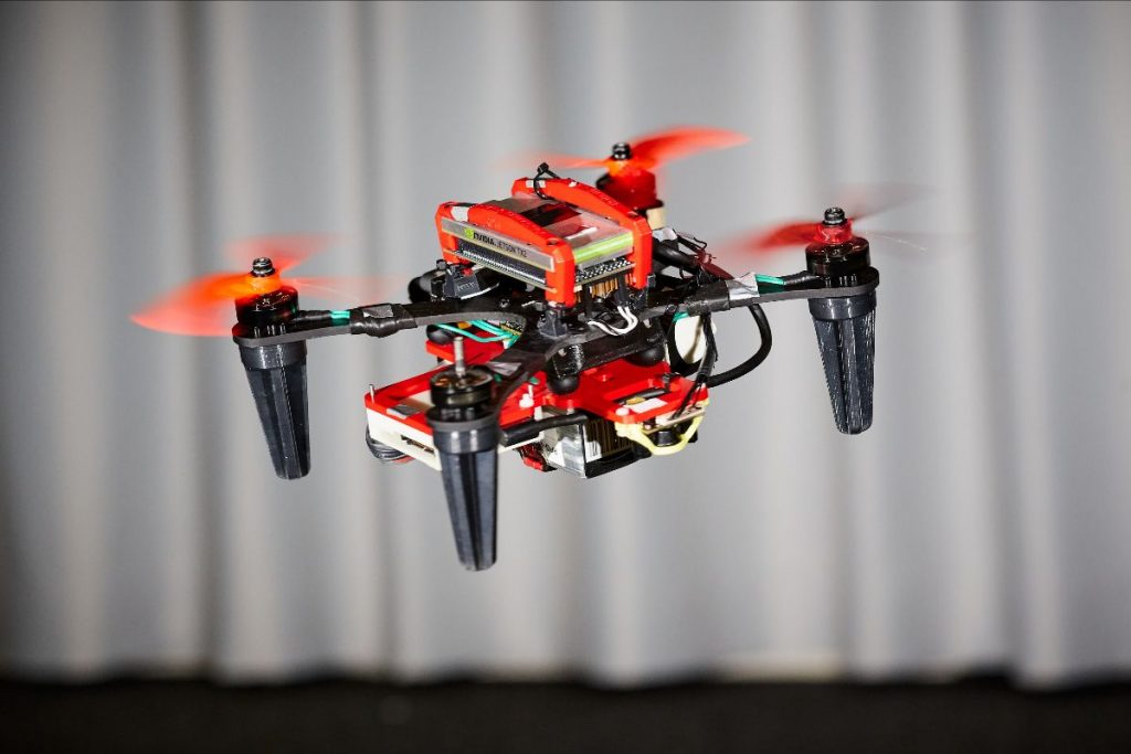
Meanwhile, researchers at École Polytechnique Fédérale de Lausanne are developing flexible multi-rotor drones that absorb the impact of a collision without breaking. (Gizmodo)

The China Academy of Aerospace Aerodynamics is readying its Caihong solar-powered long-endurance drone for its maiden flight, which is scheduled for mid-year. (Eco-Business)

Meanwhile, the China Aerospace Science and Industry Corporation has announced that it is developing drones with stealth capabilities. (Voice of America)

During an exercise, defense firm Rafael successfully launched a missile from an Israeli Navy unmanned boat. (Times of Israel)

Technology firms Thales and Unifly unveiled the ECOsystem UTM, an air traffic management system for drones. (Unmanned Systems Technology)

Norway’s government has approved a plan to establish a large test site for unmanned maritime vehicles at the Trondheim Fjord. (Phys.org)

Automaker Land Rover unveiled a search and rescue SUV equipped with a roof-mounted drone. (TechCrunch)

U.S. chipmaker NVIDIA has launched the Jetson TX2, an artificial intelligence platform that can be used in drones and robots. (Engadget)

Recent satellite images of Russia’s Gromov Flight Research Institute appear to show the country’s new Orion, a medium-altitude long-endurance military drone. (iHLS)

Technology firms Aveillant and DSNA Services are partnering to develop a counter-drone system. (AirTrafficManagement.net)

Aerospace firm Airbus has told reporters that it is serious about producing its Pop.Up passenger drone concept vehicle. (Wired)

Drones at Work

The Peruvian National Police are looking to deploy drones for counter-narcotics operations. (Business Insider)

The U.S. Air Force used a multi-rotor drone to conduct a maintenance inspection of a C-17 cargo plane. (U.S. Air Force)

India is reportedly looking to deploy U.S drones for surveillance operations along the Line of Control on the border with Pakistan. (Times of India)

The Fire Department of New York used its tethered multi-rotor drone for the first time during an apartment fire in the Bronx. (Crain’s New York)

The Michigan State Police Bomb Squad used an unmanned ground vehicle to inspect the interior of two homes that were damaged by a large sinkhole. (WXYZ)

A video posted to YouTube appears to show a woman in Washington State firing a gun at a drone that was flying over her property. (Huffington Post)

Meanwhile, a bill being debated in the Oklahoma State Legislature would remove civil liability for anybody who shoots a drone down over their private property. (Ars Technica)

In a promotional video, the company that makes Oreos used drones to dunk cookies into cups of milk. (YouTube)

The NYC Drone Film Festival will hold its third annual event this week. (YouTube)

An Arizona man who leads an anti-immigration vigilante group is using a drone to patrol the U.S border with Mexico in search of undocumented crossings. (Voice of America)

A man who attempted to use a drone to smuggle drugs into a Scottish prison has been sentenced to five years in prison. (BBC)

Industry Intel

The Turkish military has taken a delivery of six Bayraktar TB-2 military drones, two of which are armed, for air campaigns against ISIL and Turkish forces. (Defense News)

The U.S. Navy awarded Boeing Insitu a contract for RQ-21A Blackjack and ScanEagle drones. (FBO)

The U.S. Army awarded Riegl a $30,021 contract for LiDAR accessories for the Riegl RiCopter drone. (FBO)

General Atomics Aeronautical Systems awarded Hughes Network Systems a contract for satellite communications for the U.K.’s Predator B drones. (Space News)

Schiebel awarded CarteNav Solutions a contact for its AIMS-ISR software for the S-100 Camcopter unmanned helicopters destined for the Royal Australian Navy. (Press Release)

Defence Research and Development Canada awarded Ontario Drive & Gear a $1 million contract for trials of the Atlas J8 unmanned ground vehicle. (Canadian Manufacturing)

Kratos Defense and Security Solutions reported a $5.6 million contract for aerial targeted drones for the U.S. government. (Shephard Media)

Deveron UAS will provide Thompsons, a subsidiary of Lansing Trade Group and The Andersons, with drone data for agricultural production through 2018. (Press Release)

Precision Vectors Aerial selected the Silent Falcon UAS for its beyond visual line-of-sight operations in Canada. (Shephard Media)

Rolls-Royce won a grant from Tekes, a Finnish government research funding agency, to continue developing remote and autonomous shipping technologies. (Shephard Media)

Israeli drone manufacturer BlueBird is submitting an updated MicroB UAV system for the Indian army small UAV competition. (FlightGlobal)

A Romanian court has suspended a planned acquisition of Aeronautics Defense Systems Orbiter 4 drones for the Romanian army. (FlightGlobal)
Deere & Co.—a.k.a. John Deere—announced that it will partner with Kespry, a drone startup, to market drones for the construction and forestry industries. (TechCrunch)

For updates, news, and commentary, follow us on Twitter. The Weekly Drone Roundup is a newsletter from the Center for the Study of the Drone. It covers news, commentary, analysis and technology from the drone world. You can subscribe to the Roundup here.

Intel to acquire Mobileye for $15.3 billion

Source: Intel

Intel announced plans to acquire Israel-based Mobileye, a developer of vision technology used in autonomous driving applications, for $15.3 billion. Mobileye share prices jumped from $47 to $61 (the tender offering price is $63.54) on the news, a 30% premium. The purchase marks the largest acquisition of an Israeli hi-tech company ever.

Source: Frost & Sullivan;VDS Automotive SYS Konferenz 2014/

This transaction jumpstarts Intel’s efforts to enter the emerging autonomous driving marketplace, an arena much different than Intel’s present business model. The process to design and bring a chip to market involves multiple levels of safety checks and approvals as well as incorporation into car company design plans – a process that often takes 4 to 5 years – which is why it makes sense to acquire a company already versed in those activities. As can be seen in the Frost & Sullivan chart on the right, we are presently producing cars with Level 2 and Level 3 automated systems. Intel wants to be a strategic partner going forward to fully automated and driverless Level 4 and Level 5 cars.

Mobileye is a pioneer in the development of vision systems for on-board Driving Assistance Systems; providing data for decision making applications such as Mobileye’s Adaptive Cruise Control, Lane Departure Warning, Forward Collision Warning, Headway Monitoring, High Beam Assist and more. Mobileye technology is already included in BMW 5-Series, 6-Series, 7-Series, Volvo S80, XC70 and V70 models, and Buick Lucerne, Cadillac DTS and STS.

Last year, Intel reorganized and created a new Autonomous Driving Division which included strategic partnerships with, and investments in, Delphi, Mobileye and a bunch of smaller companies involved in the chipmaking and sensor process. Thus, with this acquisition, Intel gains the ability to offer automakers a larger package of all of the components they will need as vehicles become autonomous and perhaps gaining, as well, on their competitors in the field: NXP Semiconductors, Freescale Semiconductor, Cypress Semiconductor, and STMicroelectronics, the company that makes Mobileye’s chips.

Mobileye’s newest chip, the EyeQ4, designed for computer vision processing in ADAS applications, is a low-power supercomputer on a chip. The design features are described in this article by Imagination Technology.

Bottom line:

“They’re paying a huge premium in order to catch up, to get into the front of the line, rather than attempt to build from scratch,” said Mike Ramsey, an analyst with technology researcher Gartner in a BloombergTechnology article.

Developing ROS programs for the Sphero robot

You probably know the Sphero robot. It is a small robot with the shape of a ball. In case that you have one, you must know that it is possible to control it using ROS, by installing in your computer the Sphero ROS packages developed by Melonee Wise and connecting to the robot using the bluetooth of the computer.

Now, you can use the ROS Development Studio to create ROS control programs for that robot, testing as you go by using the integrated simulation.

The ROS Development Studio (RDS) provides off-the-shelf a simulation of Sphero with a maze environment. The simulation provides the same interface as the ROS module created by Melonee, so you can test your develop and test the programs on the environment, and once working properly, transfer it to the real robot.

We created the simulation to teach ROS to the students of the Robot Ignite Academy. They have to learn ROS enough to make the Sphero get out of the maze by using odometry and IMU.

Using the simulation

To use the Sphero simulation on RDS go to rds.theconstructsim.com and sign in. If you select the Public simulations, you will quickly identify the Sphero simulation.

Press the red Play button. A new screen will appear giving you details about the simulation and asking you which launch file you want to launch. The main.launch selected by default is the correct one, so just press Run.

After a few seconds the simulation will appear together with the development environment for creating the programs for Sphero and testing them.

On the left hand side you have a notebook containing information about the robot and how to program it with ROS. This notebook contains just some examples, but it can be completed and/or modified at your will. As you can see it is an iPython notebook and follows its standard. So it is up to you to modify it, add new information or else. Remember that any change you do to the notebook will be saved in a simulation in your private area of RDS, so you can come back later and launch it with your modifications.

You must know that the code included in the notebook is directly executable by selecting the cell of the code (do a single click on it) and pressing the small play button at the top of the notebook. This means that, once you press that button, the code will be executed and start controlling the Sphero simulated robot for a few time-steps (remember to have the simulation activated (Play button of the simulation activated) to see the robot move).

On the center area, you can see the IDE. It is the development environment for developing the code. You can browse there all the packages related to the simulation or any other packages that you may create.

On the right hand side, you can see the simulation and beneath it, the shell. The simulation shows the Sphero robot as well as the environment of the maze. On the shell, you can issue commands in the computer that contains the simulation of the robot. For instance, you can use the shell to launch the keyboard controller and move the Sphero around. Try typing the following:

  • $ roslaunch sphero_gazebo keyboard_teleop.launch

Now you must be able to move the robot around the maze by pressing some keys of the keyboard (instructions provided on the screen).

You can also launch there Rviz, and then watch the robot, the frames and any other additional information you may want of the robot. Type the following:

  • $ rosrun rviz rviz

Then press the Screen red icon located at the bottom-left of the screen (named the graphical tools). A new tab should appear, showing how the Rviz is loading. After a while, you can configure the Rviz to show the information you desire.

There are many ways you can configure the screen to provide more focus to what interests you the most.

To end this post, I would like to indicate that you can download the simulation to your computer at any time, by doing right-click on the directories and selecting Download. You can also clone the The Construct simulations repository to download it (among other simulations available).

If you liked this tutorial, you may also enjoy these:

See all the latest robotics news on Robohub, or sign up for our weekly newsletter.

Split-second decisions: Navigating the fine line between man and machine

Level 3 automation, where the car handles all aspects of driving with the driver on standby, is being tested in Sweden. Image courtesy of Volvo cars

Today’s self-driving car isn’t exactly autonomous – the driver has to be able to take over in a pinch, and therein lies the roadblock researchers are trying to overcome. Automated cars are hurtling towards us at breakneck speed, with all-electric Teslas already running limited autopilot systems on roads worldwide and Google trialling its own autonomous pod cars.

However, before we can reply to emails while being driven to work, we have to have a foolproof way to determine when drivers can safely take control and when it should be left to the car.

‘Even in a limited number of tests, we have found that humans are not always performing as required,’ explained Dr Riender Happee, from Delft University of Technology in the Netherlands, who is coordinating the EU-funded HFAuto project to examine the problem and potential solutions.

‘We are close to concluding that the technology always has to be ready to resolve the situation if the driver doesn’t take back control.’

But in these car-to-human transitions, how can a computer decide whether it should hand back control?

‘Eye tracking can indicate driver state and attention,’ said Dr Happee. ‘We’re still to prove the practical usability, but if the car detects the driver is not in an adequate state, the car can stop in the safety lane instead of giving back control.’

Next level

It’s all a question of the level of automation. According to the scale of US-based standards organisation SAE International, Level 1 automation already exists in the form of automated braking and self-parking.

Level 4 & 5 automation, where you punch in the destination and sit back for a nap, is still on the horizon.

But we’ll soon reach Level 3 automation, where drivers can hand over control in situations like motorway driving and let their attention wander, as long as they can safely intervene when the car asks them to.

HFAuto’s 13 PhD students have been researching this human-machine transition challenge since 2013.

Backed with Marie Skłodowska-Curie action funding, the students have travelled Europe for secondments, to examine carmakers’ latest prototypes, and to carry out simulator and on-road tests of transition takeovers.

Alongside further trials of their transition interface, HFAuto partner Volvo has already started testing 100 highly automated Level 3 cars on Swedish public roads.

Another European research group is approaching the problem with a self-driving system that uses external sensors together with cameras inside the cab to monitor the driver’s attentiveness and actions.

Blink

‘Looking at what’s happening in the scene outside of the cars is nothing without the perspective of what’s happening inside the car,’ explained Dr Oihana Otaegui, head of the Vicomtech-IK4 applied research centre in San Sebastián, Spain.

She coordinates the work as part of the EU-funded VI-DAS project. The idea is to avoid high-risk transitions by monitoring factors like a driver’s gaze, blinking frequency and head pose — and combining this with real-time on-road factors to calculate how much time a driver needs to take the wheel.

Its self-driving system uses external cameras as affordable sensors, collecting data for the underlying artificial intelligence system, which tries to understand road situations like a human would.

VI-DAS is also studying real accidents to discern challenging situations where humans fail and using this to help train the system to detect and avoid such situations.

The group aims to have its first interface prototype working by September, with iterated prototypes appearing at the end of 2018 and 2019.

Dr Otaegui says the system could have potential security sector uses given its focus on creating artificial intelligence perception in any given environment, and hopes it could lead to fully automated driving.

‘It could even go down the path of Levels 4 and 5, depending on how well we can teach our system to react — and it will indeed be improving all the time we are working on this automation.’

The question of transitions is so important because it has an impact on liability – who is responsible in the case of an accident.

It’s clear that Level 2 drivers can be held liable if they cause a fender bender, while carmakers will take the rap once Level 4 is deployed. However, with Level 3 transitions, liability remains a burning question.

HFAuto’s Dr Happee believes the solution lies in specialist insurance options that will emerge.

‘Insurance solutions are expected (to emerge) where a car can be bought with risk insurance covering your own errors, and those which can be blamed on carmakers,’ he said.

Yet it goes further than that. Should a car choose to hit pedestrians in the road, or swerve into the path of an oncoming lorry, killing its occupants?

‘One thing coming out of our discussions is that no one would buy a car which will sacrifice its owner for the lives of others,’ said Dr Happee. ‘So it comes down to making these as safe as possible.’

The five levels of automation:

  1. Driver Assistance: the car can either steer or regulate speed on its own.
  2. Partial Automation: the vehicle can handle both steering and speed selection on its own in specific controlled situations, such as on a motorway.
  3. Conditional Automation: the vehicle can be instructed to handle all aspects of driving, but the driver needs to be on standby to intervene if needed.
  4. High Automation: the vehicle can be instructed to handle all aspects of driving, even if the driver is not available to intervene.
  5. Level 5 – Full Automation: the vehicle handles all aspects of driving, all the time.

Robotic science may (or may not) help us keep up with the death of bees

Credit: SCAD

Beginning in 2006 beekeepers became aware that their honeybee populations were dying off at increasingly rapid rates. Scientists are also concerned about the dwindling populations of monarch butterflies. Researchers have been scrambling to come up with explanations and an effective strategy to save both insects or replicate their pollination functions in agriculture.

Photo: SCAD

Although the Plan Bee drones pictured above are just one SCAD (Savannah College of Art and Design) student’s concept for how a swarm of drones could handle pollinating an indoor crop, scientists are considering different options for dealing with the crisis, using modern technology to replace living bees with robotic ones.Researchers from the Wyss Institute and the School of Engineering and Applied Sciences at Harvard introduced the first RoboBees in 2013, and other scientists around the world have been researching and designing their solutions ever since.

Honeybees pollinate almost a third of all the food we consume and, in the U.S., account for more than $15 billion worth of crops every year. Apples, berries, cucumbers and almonds rely on bees for their pollination. Butterflies also pollinate, but less efficiently than bees and mostly they pollinate wildflowers.

The National Academy of Sciences said:

“Honey bees enable the production of no fewer than 90 commercially grown crops as part of the large, commercial, beekeeping industry that leases honey bee colonies for pollination services in the United States.

Although overall honey bee colony numbers in recent years have remained relatively stable and sufficient to meet commercial pollination needs, this has come at a cost to beekeepers who must work harder to counter increasing colony mortality rates.”

Florida and California have been hit especially hard by decreasing bee colony populations. In 2006, California produced nearly twice as much honey as the next state. But in 2011, California’s honey production fell by nearly half. The recent severe drought in California has become an additional factor driving both its honey yield and bee numbers down as less rain means less flowers available to pollinate.

In the U.S., the Obama Administration created a task force which developed The National Pollinator Health Strategy plan to:

  • Restore honey bee colony health to sustainable levels by 2025.
  • Increase Eastern monarch butterfly populations to 225 million butterflies by year 2020.
  • Restore or enhance seven million acres of land for pollinators over the next five years.

For this story, I wrote to the EPA specialist for bee pollination asking whether funding was continuing under the Trump Administration or whether the program itself was to be continued. No answer.

Japan’s National Institute of Advanced Industrial Science and Technology scientists have invented a drone that transports pollen between flowers using horsehair coated in a special sticky gel. And scientists at the Universities of Sheffield and Sussex (UK) are attempting to produce the first accurate model of a honeybee brain, particularly those portions of the brain that enable vision and smell. Then they intend to create a flying robot able to sense and act as autonomously as a bee.

Bottom Line:

As novel and technologically interesting as these inventions may be, the metrics will need to be near to the present costs of pollination. Or, as biologist Dave Goulson said to a Popular Science reporter, “Even if bee bots are really cool, there are lots of things we can do to protect bees instead of replacing them with robots.”

Saul Cunningham, of the Australian National University, confirmed that sentiment by showing that today’s concepts are far from being economically feasible:

“If you think about the almond industry, for example, you have orchards that stretch for kilometres and each individual tree can support 50,000 flowers,” he says. “So the scale on which you would have to operate your robotic pollinators is mind-boggling.”

“Several more financially viable strategies for tackling the bee decline are currently being pursued including better management of bees through the use of fewer pesticides, breeding crop varieties that can self-pollinate instead of relying on cross-pollination, and the use of machines to spray pollen over crops.”

Beyond 5G: NSF awards $6.1 million to accelerate advanced wireless research

The National Science Foundation (NSF) announced a $6.1 million, five-year award to accelerate fundamental research on wireless communication and networking technologies through the foundation’s Platforms for Advanced Wireless Research (PAWR) program.

Through the PAWR Project Office (PPO), award recipients US Ignite, Inc. and Northeastern University will collaborate with NSF and industry partners to establish and oversee multiple city-scale testing platforms across the United States. The PPO will manage nearly $100 million in public and private investments over the next seven years.

“NSF is pleased to have the combined expertise from US Ignite, Inc. and Northeastern University leading the project office for our PAWR program,” said Jim Kurose, NSF assistant director for Computer and Information Science and Engineering. “The planned research platforms will provide an unprecedented opportunity to enable research in faster, smarter, more responsive, and more robust wireless communication, and move experimental research beyond the lab — with profound implications for science and society.”

Over the last decade, the use of wireless, internet-connected devices in the United States has nearly doubled. As the momentum of this exponential growth continues, the need for increased capacity to accommodate the corresponding internet traffic also grows. This surge in devices, including smartphones, connected tablets and wearable technology, places an unprecedented burden on conventional 4G LTE and public Wi-Fi networks, which may not be able to keep pace with the growing demand.

NSF established the PAWR program to foster use-inspired, fundamental research and development that will move beyond current 4G LTE and Wi-Fi capabilities and enable future advanced wireless networks. Through experimental research platforms that are at the scale of small cities and communities and designed by the U.S. academic and industry wireless research community, PAWR will explore robust new wireless devices, communication techniques, networks, systems and services that will revolutionize the nation’s wireless systems. These platforms aim to support fundamental research that will enhance broadband connectivity and sustain U.S. leadership and economic competitiveness in the telecommunications sector for many years to come.

“Leading the PAWR Project Office is a key component of US Ignite’s mission to help build the networking foundation for smart communities,” said William Wallace, executive director of US Ignite, Inc., a public-private partnership that aims to support ultra-high-speed, next-generation applications for public benefit. “This effort will help develop the advanced wireless networks needed to enable smart and connected communities to transform city services.”

Establishing the PPO with this initial award is the first step in launching a long-term, public-private partnership to support PAWR. Over the next seven years, PAWR will take shape through two multi-stage phases:

  • Design and Development. The PPO will assume responsibility for soliciting and vetting proposals to identify the platforms for advanced wireless research and work closely with sub-awardee organizations to plan the design, development, deployment and initial operations of each platform.
  • Deployment and Initial Operations. The PPO will establish and manage each platform and document best practices as it progresses through the lifecycle.

“We are delighted that our team of wireless networking researchers has been selected to take the lead of the PAWR Project Office in partnership with US Ignite, Inc.,” said Dr. Nadine Aubry, dean of the college of engineering and university distinguished professor at Northeastern University. “I believe that PAWR, by bringing together academia, industry, government and communities, has the potential to make a transformative impact through advances spanning fundamental research and field platforms in actual cities.”

The PPO will work closely with NSF, industry partners and the wireless research community in all aspects of PAWR planning, implementation and management. Over the next seven years, NSF anticipates investing $50 million in PAWR, combined with approximately $50 million in cash and in-kind contributions from over 25 companies and industry associations. The PPO will disperse these investments to support the selected platforms.

Additional information can be found on the PPO webpage.

This announcement will also be highlighted this week during the panel discussion, “Wireless Network Innovation: Smart City Foundation,” at the South by Southwest conference in Austin, Texas.

UgCS photogrammetry technique for UAV land surveying missions


Figure 15: Adding 40m overshot to both ends of each survey line

UgCS is easy-to-use software for planning and flying UAV drone-survey missions. It supports almost any UAV platform, providing convenient tools for areal and linear surveys and enabling direct drone control. What’s more, UgCS enables professional land survey mission planning using photogrammetry techniques.

How to plan photogrammetry mission with UgCS

Standard land surveying photogrammetry mission planning with UgCS can be divided into following steps :

  1. Obtain input data
  2. Plan mission
  3. Deploy ground control points
  4. Fly mission
  5. Image geotagging
  6. Data processing
  7. Map import to UgCS (optional)

Step one: Obtain input data

Firstly, to reach the desired result, input settings have to be defined:

  • Required GSD (ground sampling distance – size of single pixel on ground),
  • Survey area boundaries,
  • Required forward and side overlap.

GSD and area boundaries are usually defined by the customer’s requirements for output material parameters, for example by scale and resolution of digital map. Overlap should be chosen according to specific conditions of surveying area and requirements of data processing software.

Each data processing software (e.g., Pix4D, Agisoft Photoscan, Dronedeploy, Acute 3d) has specific requirements for side and forward overlaps for different surfaces. To choose correct values, please refer to documentation of chosen software. In general, 75% forward and 60% side overlap will be a good choice. Overlapping should be increased for areas with small amount of visual cues, for example for deserts or forests.

Often, aerial photogrammetry beginners are excited about the option to produce digital maps with extremely high resolution (1-2cm/pixel), and to use very small GSD for mission planning. This is very bad practice. Small GSD will result in longer flight time, hundreds of photos for each acre, tens of hours of processing and heavy output files. GSD should be set according to the output requirements of the digital map.

Other limitations can occur. For example, GSD of 10cm/pixel is required, but designed to use a Sony A6000 camera. Based on mentioned GSD and camera’s parameters, the flight altitude would be set to 510 meters. In most countries, maximum allowed altitude of UAV’s (without special permission) is limited to 120m/400ft AGL (above ground). Taking into account the maximum allowed altitude, the maximum possible GSD in this case could be no more than 2.3cm.

Step two: Plan your mission

Mission planning consists of two stages:

  • Initial planning,
  • Route optimisation.

-Initial planning:

The first step is to set surveying area using UgCS Photogrammetry tool. Area can be set using visual cues on underlying map or using exact coordinates of edges. The result – survey area is marked with yellow boundaries (Figure 1).

Figure 1: Setting the survey area

The next step is to set GSD and overlapping for the camera in Photogrammetry tool’s settings window (Figure 2).

Figure 2: Setting camera’s Ground Sampling Distance and overlapping

To take photos in Photogrammetry tool’s setting window, define the control action of the camera (Figure 3). Set camera by distance triggering action with default values.

Figure 3: Setting camera’s control action

At this point, initial route planning is completed. UgCS will automatically calculate photogrammetry route (see Figure 4).

Figure 4: Calculated photogrammetry survey route before optimisation

-Route optimisation

To optimise the route, it’s calculated parameters should be known: altitude, estimated flight time, number of shots, etc.

Part of the route’s calculated information can be found in the elevation profile window. To access the elevation profile window (if it is not visible on screen) click the parameters icon on the route card (lower-right corner, see Figure 5), and from the drop-down menu select show elevation:

Figure 5: Accessing elevation window from Route cards Parameters settings

The elevation profile window will present an estimated route length, duration, waypoint count and min/max altitude data:

Figure 6: Route values in elevation profile window

To get other calculated values, open route log by clicking on route status indicator: the green check-mark (upper-right corner, see Figure 7) of the route card:

Figure 7: Route card and status indicator, Route log

Using route parameters, it can be optimised to be more efficient and safe.

-Survey line direction

By default, UgCS will trace survey lines from south to north. But, in most cases, it will be more optimal to fly parallel to the longest boundary line of the survey area. To change survey line direction, edit direction angle field in the photogrammetry tool. In the example, by changing angle to 135 degrees, the number of passes is reduced from five (Figure 4) to four (Figure 8) and route length is 1km instead of 1.3km.

Figure 8: Changed survey line angle to be parallel to longest boundary

-Altitude type

UgCS Photogrammetry tool has the option to define how to trace the route according to altitude, with constant altitude above ground (AGL) or above mean sea level (AMSL). Please refer to your data processing software requirements as to which altitude tracking method it recommend.

In the UgCS team’s experience, the choice of altitude type depends on desired result. For orthophotomap (standard aerial land survey output format) it is better to choose AGL to ensure constant GSD for the entire map. If the aim is to produce DEM or 3D reconstruction, use AMSL so the data processing software has more data to correctly determine ground elevation by photos in order to provide more qualitative output.

Figure 9: Elevation profile with constant altitude above mean sea level (AMSL)

In this case, UgCS will calculate flight altitude based on the lowest point of the survey area.

If AGL is selected in photogrammetry tool’s settings, UgCS will calculate the altitude for each waypoint. But in this case, terrain following will be rough if no “additional waypoints” are added (see Figure 10).

Figure 10: Elevation profile with AGL without additional waypoints

Therefore, if AGL is used, add some “additional waypoints” flags and UgCS will calculate a flight plan with elevation profile accordingly (see Figure 11).

Figure 11: Elevation profile with AGL with additional waypoints

-Speed

In general, if flight speed is increased it will minimise flight time. But high speed in combination with large camera exposure can result in blurred images. In most cases 10m/s is the best choice.

-Camera control method

UgCS supports 3 camera control methods (actions):

  1. Make a shot (trigger camera) in waypoint,
  2. Make shot every N seconds,
  3. Make shot every N meters.

Not all autopilots support all 3 camera control options. For example (quite old) DJI A2 does support all three options, but newer (starting from Phantom 3 and up to M600) cameras support only triggering in waypoints and by time. DJI promised to implement triggering by distance, but it’s not available yet.

Here are some benefits and drawbacks for all three methods:

Table 1: Benefits and Drawback for camera triggering methods

In conclusion:

  • Trigger in waypoints should be preferred when possible
  • Trigger by time should be used only if no other method is possible
  • Trigger by distance should be used when triggering in waypoints is not possible to use

To select triggering method in UgCS Photogrammetry tool accordingly, use one of three available icons:

  • Set camera mode
  • Set camera by time
  • Set camera by distance

-Glibal control

Drones, e.g., DJI Phantom 3, Phantom 4, Inspire, M100 or M600 with integrated gimbal, have the option to control camera position as part of an automatic route plan.

It is advisable to set camera to nadir position in the first waypoint, and in horizontal position before landing to prevent lenses from potential damage.

To set camera position, select the waypoint preceding the photogrammetry area and click set camera attitude/zoom (Figure 12) and enter “90” in the “Tilt” field (Figure 13).

Figure 12: Setting camera attitude
Figure 13: Setting camera position

As described previously, this waypoint should be a Stop&Turn type, otherwise the drone could skip this action.

To set camera to horizontal position, select last waypoint of survey route and click set camera attitude/zoom and enter “0” in the “Tilt” field.

-Turn types

Most autopilots or multirotor drones support different turn types in waypoints. Most popular DJI drones have three turn-types:

  • Stop and Turn: drone flies to the fixed point accurately, stays at that fixed point and then flies to next fixed point.
  • Bank Turn: the drone would fly with constant speed from one point to another without stopping.
  • Adaptive Bank Turn: It is almost the same performance like Bank Turn mode (Figure 13), but the real flight routine will be more accurately than Bank Turn.

It is advisable not to use Bank Turn for photogrammetry missions. Drone interprets Bank Turns as “recommendation destination waypoint”. The drone will fly towards this direction but will almost never pass through the waypoint. Because drone will not pass the waypoint, no action will be executed, meaning the camera will not be triggered, etc.

Adaptive Bank Turn should be used with caution because a drone can miss waypoints and, again, no camera triggering will be initiated.

Figure 14: Illustration of typical DJI drone trajectories for Bank Turn and Adaptive Bank Turn types

Sometimes, adaptive bank turn type has to be used in order to have shorter flight time compared to stop and turn. When using adaptive bank turns, it is recommended to use overshot (see below) for the photogrammetry area.

-Overshot

Initially overshot was implemented for fixed wing (airplane) drones in order to have enough space for manoeuvring a U-turn.

Overshot can be set in photogrammetry tool to add an extra segment to both ends of each survey line.

Figure 15: Adding 40m overshot to both ends of each survey line

In the example (Figure 15) can be seen that UgCS added 40m additional segments to both ends of each survey line (comparing to Figure 8).

Adding overshot is useful for copter-UAVs in two situations:

  1. When Adaptive Bank Turns are used (or similar method for non-DJI drones), adding overshot will increase the chance that drone will precisely enter survey line and camera control action will be triggered. UgCS Team recommends to specify overshot that is approximately equal to distance between the parallel survey lines.
  2. When Stop and Turn type is in use in combination with action to trigger camera in waypoints, there is a possibility that before making the shot, drone will start rotation to next waypoint – it can result in having photos with wrong orientation or blurred. To avoid that, shorter overshot has to be set, for example 5m. Don’t specify too short value (< 3m) because some drones could ignore waypoints, that are too close.
Figure 16: Example of blurred image taken by drone in rotation to next waypoint

-Takeoff point

It is important to check the takeoff area at site before flying any mission! To better explain best practice on how to set takeoff point, first discuss an example of how it should not be done. Supposing that the takeoff point in our example mission (Figure 17) would be from the point marked with the airplane-icon, and drone pilot would upload the route on the ground with set automatic mission for automatic take-off.

Figure 17: Take-off point example

Most drones in automatic takeoff mode would climb to low altitude about 3-10meters and then fly straight towards the first waypoint. Other drones would fly towards first waypoint straight from ground. Looking closely at the example map (Figure 17), some trees between the takeoff point and the first waypoint can be noticed. In this example, the drone more likely will not reach a safe altitude and will hit the trees.

Not only the surroundings can affect takeoff planning. Drone manufacturers can change drones elevation behavior in drone firmware, therefore after firmware updates it is recommended that you check drones automatic takeoff mode.

Also, a very important consideration is that most small UAVs use relative altitude for mission planing. Altitude counted relatively according to first waypoint is a second reason why an actual takeoff point should be near the first waypoint, and on the same terrain level.

UgCS Team recommends placing the first waypoint as close as possible to actual takeoff point and specifying a safe takeoff altitude (≈30m in most situations will be above any trees, see Figure 18). This is the only method that warrants safe takeoff for any mission. It also protects from any weird drone behaviour and unpredictable firmware updates, etc.

Figure 18: Route with safe take-off

-Entry point to the survey grid

In the previous example, (see Figure 18), it can be noticed, that after adding the takeoff point, the route’s survey grid entry point was changed. This is because if additional waypoint is added subsequently to the photogrammetry area, UgCS will plan to fly the survey grid starting from nearest corner to the previous waypoint.

To change the entry point to survey grid, set additional waypoint close to the desired starting corner (see Figure 19).

Figure 19: Changing survey grid entry point by adding additional waypoint

-Landing point

If no landing point will be added outside the photogrammetry area after the survey mission, the drone will fly and hover in the last waypoint. There are two options for landing:

  1. Take manual control over the drone and fly to landing point manually,
  2. Activate the Return Home command in UgCS or from Remote Controller (RC).

In situations when the radio link with the drone is lost, for example if the survey area is large or there are problems with the remote controller, depending on the drone and it’s settings, one of these actions can occur:

  • Drone will return to home location automatically if lost radio link with ground station,
  • Drone will fly to last waypoint of survey area and hover as long as battery capacity will enable that, then: drone will perform emergency landing, or it will try to fly to home location.

The recommendation is to add an explicit landing points to the route in order to avoid relying on unpredictable drone behavior or settings.

If the drone doesn’t support automatic landing, or the pilot prefers to land manually, place the route’s last waypoint over the planned landing point with an altitude for comfortable manual drone descending and landing above any obstacles in the surrounding area. In general 30m is best choice.

-Action execution

Photogrammetry tool has a magic parameter “Action Execution” with three possible values:

  • Every point
  • At start
  • Forward passes

This parameter defines how and where camera actions specified for photogrammetry tool will be executed.

The most useful option for photogrammetry/survey missions is to set forward passes, the drone will make photos only on survey lines, but will not make excess photos on perpendicular lines.

-Complex survey areas

UgCS enables photogrammetry/survey mission planning for irregular areas, having functionality to combine any number of photogrammetry areas in one route, avoiding splitting the area in separate routes.

For example, if a mission has to be planned for two fields connected in a T-shape, and if these two fields are marked as one photogrammetry area, the whole route will not be optimal, regardless any direction of survey lines.

Figure 20: Complex survey area before optimisation

If the survey area is marked as two photogrammetry areas within one route, survey lines for each area can be optimised individually (see Figure 21).

Figure 21: Optimised survey flight passes for each part of a complex photogrammetry area

Step three: deploy ground control points

Ground control points are mandatory if the survey output map has to be precisely aligned to coordinates on Earth.

There are lots of discussions about the necessity of ground control points in cases when a drone is equipped with Real Time Kinematics (RTK) GPS receivers with centimeter-level accuracy. This is useful, but the drone coordinates are not in themselves sufficient because, for precise map aligning, image center coordinates are necessary.

Data processing softwares like Agisoft Photoscan, Dronedeplay, Pix4d, Icarus OneButton and others will produce very accurate maps using geotagged images, but the real precision of the map will not be known without ground control points.

Conclusion: ground control points have to be used to create survey-grade result. For a map with approximate precision, it is sufficient to rely just on RTK GPS and the capabilities of data processing software.

Step four: fly your mission

For carefully planned missions, flying it is the most straightforward step. Mission execution differs according to the type of UAV and equipment used, therefore it will not be described in detail in this article (please refer to equipment’s and UgCS documentation).

Important issues before flying:

  • In most countries there are strict regulations for UAV usage. Always comply with the regulations! Usually these rules can be found on web-site of local aviation authority.
  • In some countries special permission for any kind of aerial photo/video shooting is needed. Please check local regulations.
  • In most cases missions are planned before arriving to flying location (e.g., in office, at home) using satellite imaginary from Google maps, Bing, etc. Before flying always check actual circumstances at the location. There could be a need to adjust take-off/landing points, for example, to avoid tall obstacles (e.g., trees, masts, power lines) in your survey area.

Step five: image geotagging

Image geotagging is optional if ground control points were used, but almost any data processing software will require less time to process geotagged images.

Some of the latest and professional drones with integrated cameras can geotag images automatically during flight. In other cases images can be geotagged in UgCS after flight.

Very important: UgCS uses the telemetry log from drone, that is received via radio channel, to extract the drone’s altitude for any given moment (when pictures were taken). To geotag pictures using UgCS, assure robust telemetry reception during flight.

For detailed information how to geotag images using UgCS refer to UgCS User Manual.

Step six: data processing

For data processing, use third party software or services available on the market.

From UgCS Team experience, the most powerful and flexible software is Agisoft Photoscan (http://www.agisoft.com/), but sometimes too much user input is required to get necessary results. The most uncomplicated solution for users is online service Dronedeploy (https://www.dronedeploy.com/). All other software packages and services will fit somewhere between these two in terms of complexity and power.

Step seven (optional): import created map to UgCS

Should the need arise for the mission to be repeated in the future, UgCS enables importing the GeoTiff file as a map layer and using it for mission planning. More detailed instructions can be found in UgCS User Manual. See the result of an imported map created using UgCS photogrammetry tool imported as GeoTiff file in Figure 22.

Figure 22: Imported GeoTiff map as layer. The map is output of a Photogrammetry survey mission panned with UgCS

Visit the UgCS homepage

Download this tutorial as a PDF

If you liked this tutorial, you may also enjoy these:

See all the latest robotics news on Robohub, or sign up for our weekly newsletter.

Page 429 of 430
1 427 428 429 430