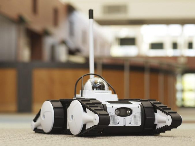
When building a new robot mechanical engineers always ask me: how close can different antennas be to one another? It is not uncommon to try squeezing 5+ antennas on a single robot (GPS, GPS2 for heading, RTK, joystick, e-stop, communications, etc..). So what is the proper response? The real answer is that it depends heavily on the environment. However, below are the rules of thumb I have learned and have been passed down to me for antenna separation. I do want to give a disclaimer some of this has been passed down as rules of thumb and may not be 100% correct.
Here is the rule: The horizontal distance between antennas should be greater than 1/4 of its wavelength (absolute minimum separation), but it should not be located at the exact multiples of its wavelength (maybe avoid the first 3-4 multiples). If multiple frequency antennas are near each other, then use the spacing distance of the lower frequency antenna, or even better, try to satisfy the rule for both frequencies.
| Device | Frequency | Wavelength | 1/4 Wavelength |
|---|---|---|---|
| WiFi 802.11 | 5.8GHz | 5.17cm | 1.29cm |
| WiFi 802.11 | 2.4GHz | 12.49cm | 3.12cm |
| GPS* | 1.227GHz | 24.43cm | 6.11cm |
| Radios | 900MHz | 33.3cm | 8.33cm |
Here is a nice wavelength calculator I just found to generate the table above.
* If you are using two GPS antennas to compute heading then this does not apply. These numbers are strictly for RF considerations.
So, for example, if you have a GPS antenna and a WiFi 2.4GHz antenna you would want them to be separated by at least (more is better, within reason) 8.33cm. And you should avoid putting them at exactly 24.43cm or 33.3cm from each other.
This rule seems to work with the low power antennas that we typically use in most robotics applications. I am not sure how this would work with high power transmitters. For higher power transmitting antennas, you might want greater separation. The power drops off pretty quickly with distance (proportional to the square of the distance).
I also try to separate receive and transmit antennas (as a precaution) to try and prevent interference problems.
An extension of the above rule is ground planes. Ground planes are conductive reference planes that are put below antennas to reflect the waves to create a predictable wave pattern and can also help prevent multipath waves (that are bouncing off the ground, water, buildings, etc…). The further an antenna is from the ground (since the ground can act as a ground plane), the more likely having a ground place becomes necessary. In its simplest form, a ground plane is a piece of metal that extends out from the antennas base at least 1/4 wavelength in each direction. Fancy ground planes might just be several metal prongs that stick out. A very common ground plane is the metal roof of a vehicle/robot.
Note: Do not confuse ground planes with RF grounds, signal grounds, DC grounds, etc…

An example of building a ground plane can be with a GPS antenna. It should be mounted in the center of a metal roofed robot/car or on the largest flat metal location. This will minimize the multipath signals from the ground. If there is no flat metal surface to mount the antenna you can create a ground plane by putting a 12.22cm diameter metal sheet directly below the antenna (about 1/2 the signals wavelength, which gives 1/4 wavelength per side).
Note: Some fancy antennas do not require that you add a ground plane. For example, the Novatel GPS antennas do NOT require you to add a ground plane, as described above.
Other things to watch out for are shadowing between the antennas and sensors and the fresnel zone. For more information on the fresnel zone, and why antennas are not actually just line of site, click here.