A robot that can put a surgical gown on a supine mannequin
Time of Flight Forges Ahead: Design Tips to Boost 3D Performance and Cut Integration Time & Cost
Time of Flight Forges Ahead: Design Tips to Boost 3D Performance and Cut Integration Time & Cost
Touchy subject: 3D printed fingertip ‘feels’ like human skin
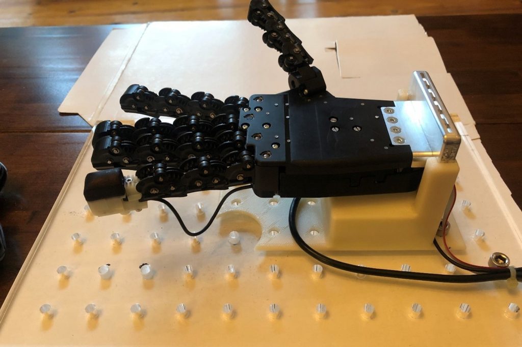
Robotic hand with a 3D-printed tactile fingertip on the little (pinky) finger. The white rigid back to the fingertip is covered with the black flexible 3D-printed skin.
Machines can beat the world’s best chess player, but they cannot handle a chess piece as well as an infant. This lack of robot dexterity is partly because artificial grippers lack the fine tactile sense of the human fingertip, which is used to guide our hands as we pick up and handle objects.
Two papers published in the Journal of the Royal Society Interface give the first in-depth comparison of an artificial fingertip with neural recordings of the human sense of touch. The research was led by Professor of Robotics & AI (Artificial Intelligence), Nathan Lepora, from the University of Bristol’s Department of Engineering Maths and based at the Bristol Robotics Laboratory.
“Our work helps uncover how the complex internal structure of human skin creates our human sense of touch. This is an exciting development in the field of soft robotics – being able to 3D-print tactile skin could create robots that are more dexterous or significantly improve the performance of prosthetic hands by giving them an in-built sense of touch,” said Professor Lepora.
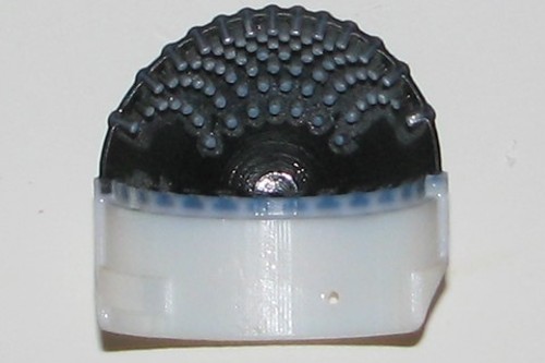
Cut-through section on the 3D-printed tactile skin. The white plastic is a rigid mount for the flexible black rubber skin. Both parts are made together on an advanced 3D-printer. The ‘pins’ on the inside of the skin replicate dermal papillae that are formed inside human skin.
Professor Lepora and colleagues created the sense of touch in the artificial fingertip using a 3D-printed mesh of pin-like papillae on the underside of the compliant skin, which mimic the dermal papillae found between the outer epidermal and inner dermal layers of human tactile skin. The papillae are made on advanced 3D-printers that can mix together soft and hard materials to create complicated structures like those found in biology.
“We found our 3D-printed tactile fingertip can produce artificial nerve signals that look like recordings from real, tactile neurons. Human tactile nerves transmit signals from various nerve endings called mechanoreceptors, which can signal the pressure and shape of a contact. Classic work by Phillips and Johnson in 1981 first plotted electrical recordings from these nerves to study ‘tactile spatial resolution’ using a set of standard ridged shapes used by psychologists. In our work, we tested our 3D-printed artificial fingertip as it ‘felt’ those same ridged shapes and discovered a startlingly close match to the neural data,” said Professor Lepora.
“For me, the most exciting moment was when we looked at our artificial nerve recordings from the 3D-printed fingertip and they looked like the real recordings from over 40 years ago! Those recordings are very complex with hills and dips over edges and ridges, and we saw the same pattern in our artificial tactile data,” said Professor Lepora.
While the research found a remarkably close match between the artificial fingertip and human nerve signals, it was not as sensitive to fine detail. Professor Lepora suspects this is because the 3D-printed skin is thicker than real skin and his team is now exploring how to 3D-print structures on the microscopic scale of human skin.
“Our aim is to make artificial skin as good – or even better – than real skin,” said Professor Lepora.
PAPERS
- Artificial SA-I, RA-I and RA-II/vibrotactile afferents for tactile sensing of texture. Nicholas Pestell and Nathan F. Lepora. Journal of The Royal Society Interface, 19, 20210603. http://doi.org/10.1098/rsif.2021.0603
- Artificial SA-I and RA-I afferents for tactile sensing of ridges and gratings. Nicholas Pestell, Thom Griffith and Nathan F. Lepora. Journal of The Royal Society Interface, 19, 20210822. https://doi.org/10.1098/rsif.2021.0822
On-the-fly reconfigurable magnetic slime used as a robot
ATX West and IME West 2022 Product Preview
Touchy subject: 3D printed fingertip ‘feels’ like human skin
Robots dress humans without the full picture
Drones and driverless cars could help with Ukraine’s humanitarian crisis
Three Reasons to Robotize Soldering Operations
A new approach that could improve how robots interact in conversational groups
Learn How To Protect Your Business with AI for Visual Inspection – Pleora Webinar Live April 6, 2022
Exoskeletons with personalize-your-own settings
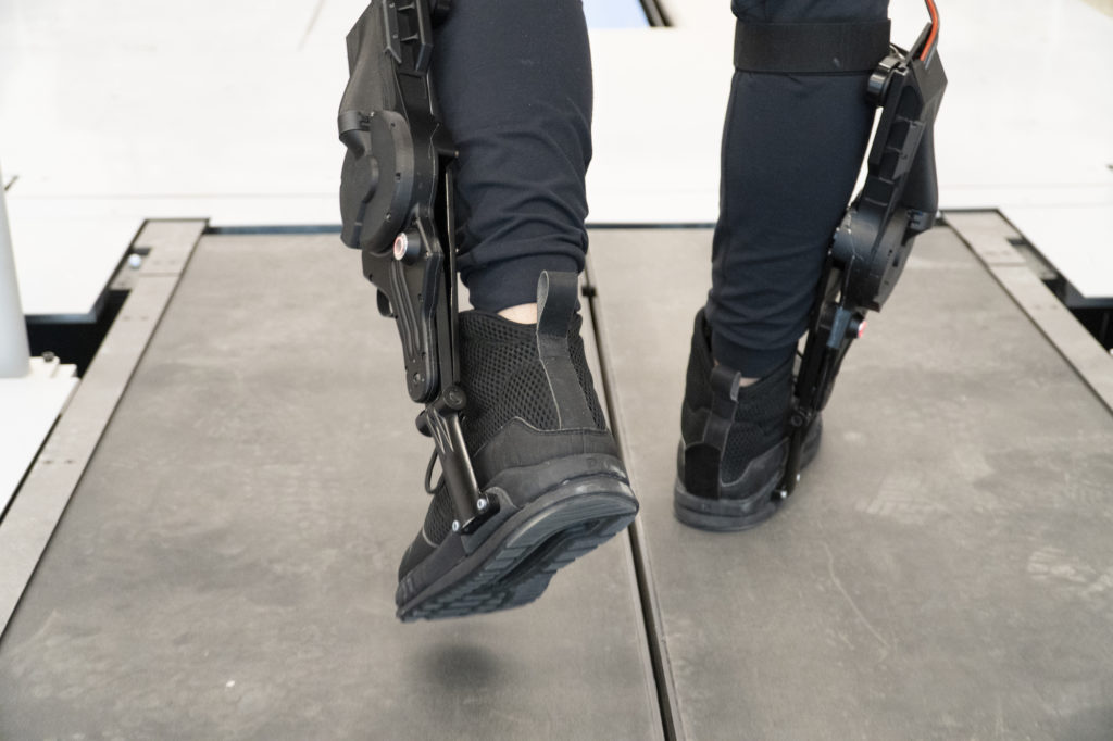
Leo Medrano, a PhD student in the Neurobionics Lab at the University of Michigan, tests out an ankle exoskeleton on a two-track treadmill. Researchers were able to give the exoskeleton user direct control to tune its behavior, allowing them to find the right torque and timing settings for themselves.
By Dan Newman
To transform human mobility, exoskeletons need to interact seamlessly with their user, providing the right level of assistance at the right time to cooperate with our muscles as we move.
To help achieve this, University of Michigan researchers gave users direct control to customize the behavior of an ankle exoskeleton.
Not only was the process faster than the conventional approach, in which an expert would decide the settings, but it may have incorporated preferences an expert would have missed. For instance, user height and weight, which are commonly used metrics for tuning exoskeletons and robotic prostheses, had no effect on preferred settings.
“Instead of a one-size-fits-all level of power, or using measurements of muscle activity to customize an exoskeleton’s behavior, this method uses active user feedback to shape the assistance a person receives,” said Kim Ingraham, first author of the study in Science Robotics, and a recent mechanical engineering Ph.D. graduate.
Experts usually tune the wide-ranging settings of powered exoskeletons to take into account the varied characteristics of human bodies, gait biomechanics and user preferences. This can be done by crunching quantifiable data, such as metabolic rate or muscle activity, to minimize the energy expended from a user, or more simply by asking the user to repeatedly compare between pairs of settings to find which feels best.
What minimizes energy expenditure, however, may not be the most comfortable or useful. And asking the user to select between choices for numerous settings could be too time consuming and also obscures how those settings might interact with each other to affect the user experience.
By allowing the user to directly manipulate the settings, preferences that are difficult to detect or measure could be accounted for by the users themselves. Users could quickly and independently decide what features are most important—for example, trading off comfort, power or stability, and then selecting the settings to best match those preferences without the need for an expert to retune.
“To be able to choose and have control over how it feels is going to help with user satisfaction and adoption of these devices in the future,” Ingraham said. “No matter how much an exoskeleton helps, people won’t wear them if they are not enjoyable.”
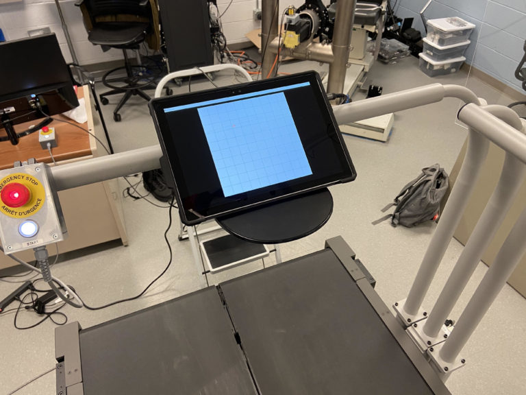
By allowing the user to directly manipulate the exoskeleton’s settings using a tablet while on a treadmill, preferences that are difficult to detect or measure, such as comfort, could be accounted for by the users themselves. Courtesy Kim Ingraham
To test the feasibility of such a system, the research team outfitted users with Dephy powered ankle exoskeletons and a touch screen interface that displayed a blank grid. Selecting any point on the grid would alter the torque output of the exoskeleton on one axis, while changing the timing of that torque on the alternate axis.
When told to find their preference while walking on a treadmill, the set of users who had no previous experience with an exoskeleton were, on average, able to confirm their optimal settings in about one minute, 45 seconds.
“We were surprised at how precisely people were able to identify their preferences, especially because they were totally blinded to everything that was happening—we didn’t tell them what parameters they were tuning, so they were only selecting their preferences based on how they felt the device was assisting them,” Ingraham said.
In addition, user preference changed over the course of the experiment. As the first-time users gained more experience with the exoskeleton, they preferred a higher level of assistance. And, those already experienced with exoskeletons preferred a much greater level of assistance than the first-time users.
These findings could help determine how often retuning of an exoskeleton needs to be done as a user gains experience and supports the idea of incorporating direct user input into preference for the best experience.
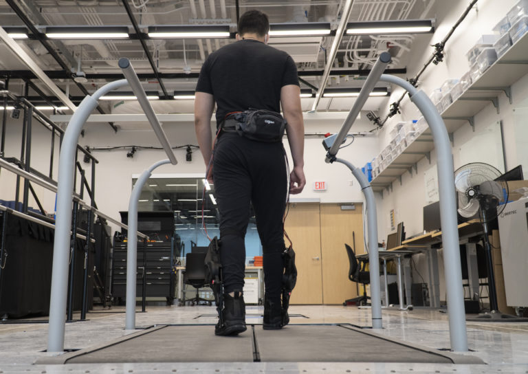
The ankle exoskeleton, from Dephy Inc., provides assistance when stepping off with the foot. An expert usually tunes the precise machines’ wide-ranging settings to take into account the varied characteristics of human bodies, gait biomechanics, and user preferences.
“This is fundamental work in exploring how to incorporate people’s preference into exoskeleton control,” said Elliott Rouse, senior author of the study, an assistant professor of mechanical engineering and a core faculty member of the Robotics Institute. “This work is motivated by our desire to develop exoskeletons that go beyond the laboratory and have a transformative impact on society.
“Next is answering why people prefer what they prefer, and how these preferences affect their energy, their muscle activity, and their physiology, and how we could automatically implement preference-based control in the real world. It’s important that assistive technologies provide a meaningful benefit to their user.”
The research was supported by the National Science Foundation, the D. Dan and Betty Kahn Foundation and the Carl Zeiss Foundation in cooperation with the German Scholars Organization, in addition to hardware and technical assistance from Dephy Inc. Ingraham is now a postdoctoral researcher at the University of Washington.
Extra: Interview with the research team
What is the history of this research question?
One of the most challenging parts of designing assistive robotic technologies is understanding how we should apply assistance to the human body in order to best meet the user’s goals. Much of the research to date has focused on designing the assistance from lower-limb robotic exoskeletons in order to reduce the energy required to walk. While reducing the energy required to walk may be valuable for applications that require users to walk long distances, there are many other factors that people may wish to prioritize when using a robotic exoskeleton during their daily lives. Users may want to prioritize any number of subjective metrics, like comfort, balance, stability, or effort. In our research, we wanted to capture some of these metrics simultaneously by asking individual users to find their preference in how the exoskeleton assists them.
Why should people care about this?
For exoskeletons to transform human mobility, they need to to act synergistically with their user by providing meaningful assistance but not interfering with their normal walking mechanics. Moreover, these devices must be comfortable to wear and user satisfaction must be high in order for people to want to use exoskeletons during their daily routines. Therefore, understanding what users prefer in the context of exoskeleton assistance is crucial to the development and translation of these technologies. Additionally, human mobility is complex, and we constantly encounter new terrains, situations, and environments that require us to adapt our gait in novel ways. It is impossible to capture in the lab or even predict all the situations that individuals will encounter using an exoskeleton in their daily lives. Therefore, giving users direct control over some elements of their exoskeleton assistance allows the user to provide a rich source of situation-specific information that can help the machine decide how to best assist the user in that given moment.
What excites you most about this finding?
Our study showed that people have clear preferences in how they want a lower-limb exoskeleton to assist them, and that they find these preferences quickly and reliably based only on their perception of how the device was assisting them. This finding opens the doors to understanding the complex interactions between the human and the machine, and will directly inform how we design exoskeleton assistance in the future.
What are your next steps? What should other researchers do next?
We are excited about understanding why users preferred a particular assistance profile and how preferred assistance relates to biomechanical, behavioral, and energetic outcomes.
Careers in robotics: Should you get a PhD or go into industry?
So you are considering a PhD in robotics! Before you decide to apply, here are some things to consider.
What is a PhD?
A PhD is a terminal degree, meaning it is the highest degree that you can earn. Almost without exception, people only earn one PhD. This degree is required for some jobs, mostly in academia, but is often just considered equivalent to years worked in industry. For some positions, hiring managers may even prefer to hire people without PhDs. A PhD is a paid (though not well paid) position at a university that lasts for between 4 and 10 years. To learn more about the PhD process, check out this previous post.
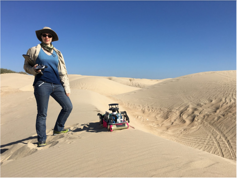
The author on a field trip to Oceano Dunes in California. She is controlling RHex, a six-legged robot, outfitted with sensors to study dune migration.
The day-to-day life of a PhD student versus an industry professional
The process of earning the PhD is very different from the process of earning a bachelor’s or a master’s degree. It is more like an internship or a job. The first two or so years of any PhD program will be largely coursework, but even at this stage you will be balancing spending time on your courses against spending time on research – either because you are rotating through different labs, because you are performing research for a qualifier, or because your advisor is attaching you to an existing research project to give you some experience and mentorship before you develop your own project. This means that getting a PhD is not actually a way to avoid “getting a job” or to “stay in school” – it is actually a job. This also means that just because you are good at or enjoy coursework does not mean you will necessarily enjoy or excel in a PhD program, and just because you struggled with coursework does not mean you will not flourish in a PhD program. After you are done with coursework, you will spend all of your time on research. Depending on the day, that can mean reading textbooks and research papers, writing papers, making and giving presentations, teaching yourself new skills or concepts, programming or building robots, running experiments, and mentoring younger students. If you excelled at either conducting research as an undergraduate or very open-ended course projects much more than typical coursework, you’ll be much more likely to enjoy research as a PhD student.
Types of goal setting in academia and industry
In course work, and in industry jobs with a good manager, you are given relatively small, well defined goals to accomplish. You have a team (your study group, your coworkers) who are all working towards the same goal and who you can ask for help. In a PhD program, you are largely responsible for narrowing down a big research question (like “How can we improve the performance of a self-driving car?”) into a question that you can answer over the course of a few years’ diligent work (“Can we use depth information to develop a new classification method for pedestrians?”). You define your own goals, often but not always with the advice of your advisor and your committee. Some projects might be team projects, but your PhD only has your name on it: You alone are responsible for this work. If this sounds exciting to you, great! But these are not good working conditions for everybody. If you do not work well under those conditions, know that you are no less brilliant, capable, or competent than someone who does. It just means that you might find a job in industry significantly more fulfilling than a job in academia. We tend to assume that getting a PhD is a mark of intelligence and perseverance, but that is often not the case — sometimes academia is just a bad match to someone’s goals and motivations.
Meaning and impact
Academic research usually has a large potential impact, but little immediate impact. In contrast, industry jobs generally have an impact that you can immediately see, even if it is very small. It is worth considering how much having a visible impact matters to you and your motivation because this is a major source of PhD student burnout. To give a tangible example, let’s say that you choose to do research on bipedal robot locomotion. In the future, your work might contribute to prostheses that can help people who have lost legs walk again, or to humanoid robots that can help with elder care. Is it important to you that you can see these applications come to fruition? If so, you might be more fulfilled working at a company that builds robots directed towards those kinds of tasks instead of working on fundamental research that may never see application in the real world. The world will be better for your contributions regardless of where you make them – you just want to make sure you are going to make those impacts in a way that allows you to find them meaningful!
Pay and lifetime earning potential
Engineers are significantly better paid in industry than academia. Since working in industry for a minimum of five to ten years and getting a PhD are often considered equivalent experience for the purposes of many job applications, even the time spent getting a PhD – where you will earn much less than you would in industry – can mean that you give up a substantial amount of money. Let’s say that an entry-level engineering job makes $100,000 per year, and a graduate student earns $40,000. If your PhD takes 6 years, you lose out on $60,000 x 6 = $360,000 of potential pay. Consider also that a PhD student’s stipend is fairly static, whereas you can expect to have incremental salary increases, bonuses, and promotions in an industry job, meaning that you actually lose out on at least $400,000. This is a totally valid reason to either skip the PhD process completely, or to work in industry for a few years and build up some savings before applying to PhD programs.
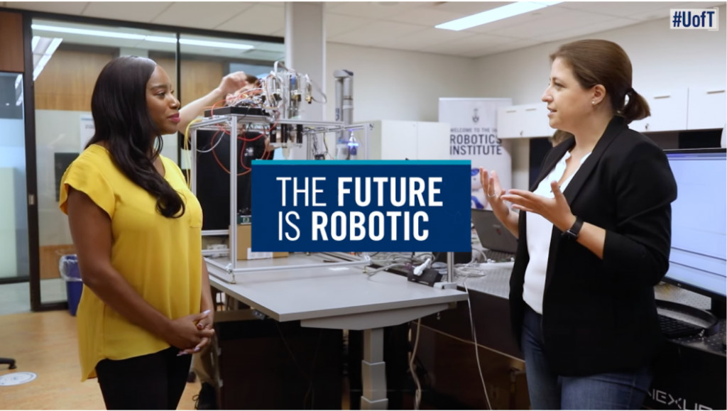
Robotics Institute at University of Toronto
How do I know what I want?
It’s hard! If you’re still uncertain, remember that you can gain a few years of work experience in industry before going back to get the PhD, and will likely be considered an even stronger candidate than before. Doing this allows you to build up some savings and become more confident that you really do want to get that PhD.
Thinking through these questions might help you figure out what direction you want to go:
- Are you much more motivated to do class projects that you are allowed to fully design yourself?
- When you think about something small you built being used daily by a neighbor, how do you feel?
- Is your desire to get a PhD because of the prestige associated with the degree, or the specific job opportunities it opens up?