Hands on ground robot & drone design series part I: mechanical & wheels

This is a new series looking at the detailed design of various robots. To start with we will be looking at the design of two different robots that were used for the DARPA Subterranean Challenge. Both of these robots were designed for operating in complex subterranean environments, including Caves, Mines & Urban environments. Both of these robots presented are from the Carnegie Mellon University Explorer team. While I am writing these posts, this was a team effort that required many people to be successful. (If anyone on Team Explorer is reading this, thank you for everything, you are all awesome.)

These posts are skipping the system requirements step of the design process. See here for more details on defining system requirements.
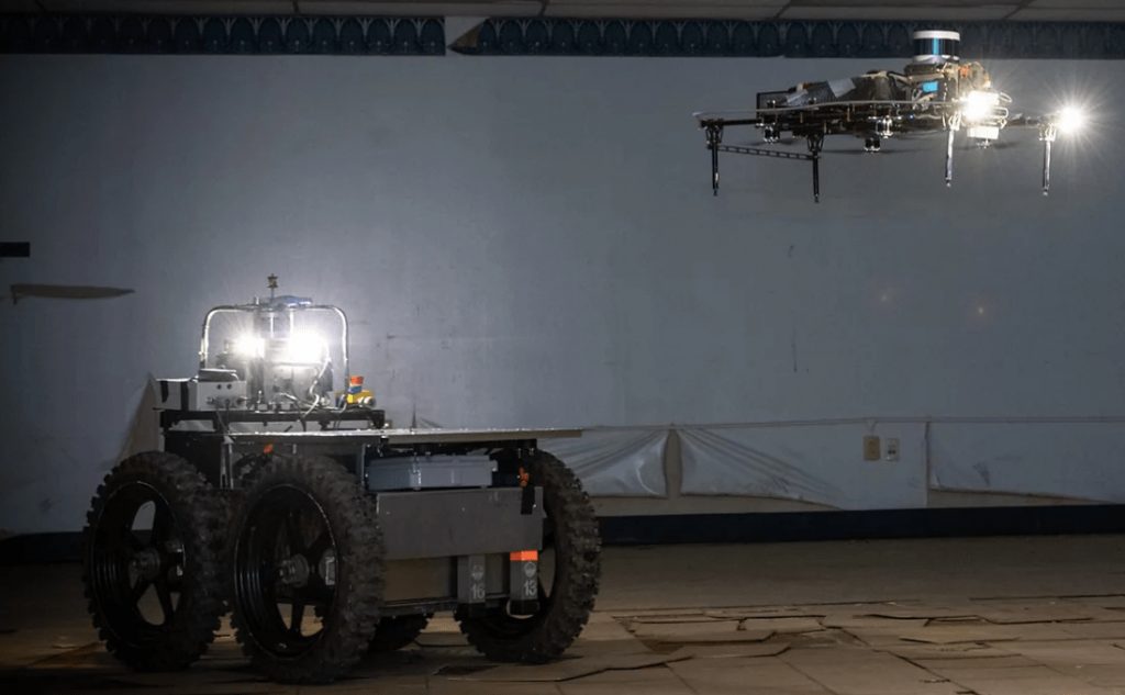
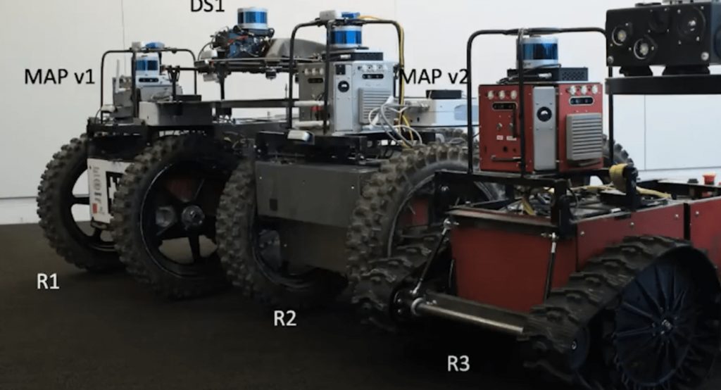
SubT Ground UGV and DS Drone ImageTeam Explorer R1 Ground Robot and DS Drone [Source]

R3 Ground robot (UGV)

For the SubT challenge three ground vehicles were developed all of a similiar design. The ground robots were known with the moniker of R#, where # is the order we built them in. The primary difference between the three versions are

R1 – Static Chassis, so the chassis has minimal ground compliance when driving over obstacles and uneven surfaces. R1 was initially supposed to have a differencing mechanism for compliance, however due to time constraints it was left out from this first version. R1 is pictured above.

R2 – Has the differencing mechanism and was designed as initially planned.

R3 – Is almost identical to R2, but smaller. This robot was built for navigating smaller areas and also to be able to climb up and down steps. It also uses different motors for the driving the wheels.

DS drone

The original drone design used by Team Explorer called their drones D1, D2, etc.. This let a combination of UGV +Drone go by joint designations such as R2D2. Early on, the team switched to a smaller drone design that was referred to as DS1, DS2, etc.. Where DS is short for Drone Small.

The drone design post are split into two sections. The first is about the actual drone platform, and the second is about the payload that sat on top of the drone.

Mechanical & wheels
Robot size decision

After we have the list of system requirements we start with the design of the mechanical structure of the robot. In this case we decided that a wheeled robot would be best. We wanted to have the largest wheels possible to help climb over obstacles, however, we also needed to keep our sensors at the top of the vehicle above the wheels and be able to fit in openings 1 x 1 meters. These requirements set the maximum size of the robot as well as the maximum size of the wheels.
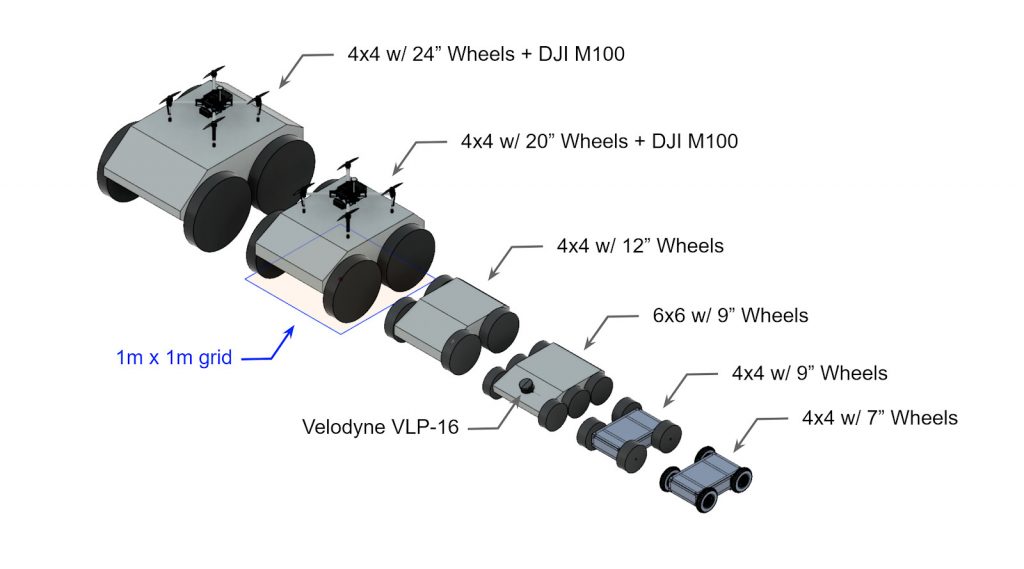
The final dimensions of the first two vehicles (R1 and R2) were around (L x W x H) 1.2 x 0.8 x 0.8 meters (3.9 x 2.6 x 2.6 ft). The third smaller vehicle was around 1 x 0.6 m (3.2 x 1.9 ft) and designed to fit through 0.7×0.7 m openings.

Steering approach

Early on we also needed to determine the method of driving. Do we want wheels or tracks? Do we want to steer with ackerman steering, rocker-bogie, skid steer, etc.?

See here for more details on steering selection.

We chose to use a skid steer four wheeled drive approach for the simplicity of control and the ability to turn in place (point turns). At the start of the competition we were not focused on stair climbing, which might have changed some of our design decisions.

Suspension

The next step was to determine the suspension type. A suspension is needed so that all four of the wheels make contact with the ground. If the robot had a static fixed frame only three of the wheels might make contact with the ground when on uneven surfaces. This would reduce our stability and traction.

We decided early on that we wanted a passive suspension for the simplicity of not having active components. With a passive suspension we were looking at different type of body averaging. We roughly had two choices, front-pivot or side-to-side.
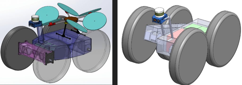
Left image shows a front-pivot approach. Right image shows a side-to-side differencing method.

We decided to choose the front-pivot method, however we decided to make the pivot be roughly centered in the vehicle. This allowed us to put all of the electronics in the front and the batteries in the rear. The front-pivot method we felt would be better for climbing up stairs and for climbing over obstacles on level’ish terrain. Also importantly this approach made it easier to carry a drone on the ground vehicle.

Chassis design

At this point we started designing the chassis. This was an important step so that we could estimate the total weight in order to spec the drive-train. Ideas for the chassis were everything from building with 80/20 to building an aluminum frame and populating it with components, to a solid welded chassis. We selected to use a welded steel tube chassis for the strength. We needed a robot that could survive anything we did to it. This proved to be a wise decision when the robot crashed or fell over cliffs. The downside of the steel was increased mass.

For the pivot we found a large crossed roller bearing that we were able to use to attach the two steel boxes together. The large bore in the middle was useful for passing wires/cables through for batteries, motors, etc…
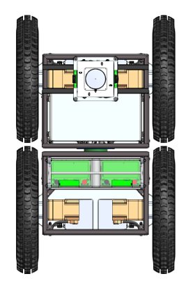
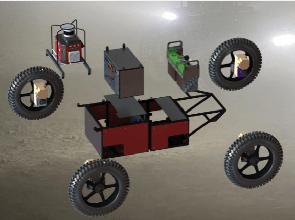
Part of the chassis design was also determining where all of the components should mount. Having the batteries (green boxes in image above) in the rear helps us climb obstacles. Other goals were to keep the ground clearance as high as possible while keeping the center of gravity (CG) as low as possible. Since those are competing goals, part of the design process was to develop a happy medium.

In order to maintain modularity for service, each wheel module had the motor controller, motor, gear box, and bearing block as a solid unit that could be swapped between robots if there was any issues. This also allowed most of the wiring to be part of that block. The only cables that needed to be connected to each of the modules from the robot were power, CAN communications, and the emergency stop line; all of which were connectorized.

For electronics on R1 and R2 we built an electronics box that was separate from the robot and could be removed from the robot as needed. On R3 we built the electronics into the robot itself. This modular approach was very useful when we had to do some welding to the chassis post-build for modifications. The downside of the modular approach for electronics was that working in the electronics box was more difficult then in the open R3. Also the time for fabricating and wiring the R1/R2 electronics boxes was considerably more than the open R3 electronics. We also had several failures during testing related to the connectors from the electronics boxes.

Wheel design

We debated a lot about what type of wheel to use, ultimately we used motorcycle wheels due to the simplicity of obtaining them and mounting them. The wheel diameter we desired also lined up very well with motorcycle wheels. In order to get better traction and ability to climb over obstacles we liked the wider tires.

R1 and R2 had a wheel diameter of 0.55m, R3 had a wheel diameter of 0.38m. This gave R1 and R2 a ground clearance of 0.2m, and R3 a ground clearance of 0.12m.

The wheel hubs ended up being a different story. We found solid metal rims that we had to machine large amounts of metal out of in order to balance the strength and the weight.

The R1 and R2 robots were around 180kg (400lb)*, the wheels were for a vehicle significantly heavier. As such we put a small amount of pressure in the wheels to keep them from falling off, however we tried to keep the pressure low to increase the ground compliance of the wheels. This method added a very small amount of compliance, we tried removing some of the rubber from the sidewalls, but was not able to get a happy medium between limiting the wheel deforming during point turns and increasing ground compliance.

We were also concerned how the motorcycle tires would do when point turning and if we would rip the wheels from the rims. To counter this we installed a beadlock system into each of the wheels. The beadlock was a curved segment installed in multiple places to sandwich the tire to the rim. We never had a wheel separate from the rim, so our approach definitely worked, however it was a pain to install.

*R3 was around 90 kg (200 lbs). We tried using different wheels and tracks to get R3 to climb stairs well. However that story is for another post…

The black rims were solid metal that we machined the wedges into in order to lightweight them. The 3 metal posts in those wedges are the beadlock tensioning bolts. You can also see the castle nut and pin that holds the wheel to the axle. This image is from R2, you can see the gap between the front and rear sections of the robot where the pivot is.

Drive-train selection

Now that we had a mass estimate and system requirements for speed and obstacle clearance we can start to spec the drive-train. The other piece of information that we needed and had to discuss with the electrical team was the voltage of the battery. Different bus voltages greatly affects the motors available for a given speed and torque. We decided on a 51.2v nominal bus voltage. This presented a problem since it was very hard to find the speed/torques we wanted at that voltage. We ended up selecting a 400W 1/2HP motor+gearbox from Oriental Motors with a parallel 100:1 gearbox that allows us to drive at a maximum speed of 2.5m/s.
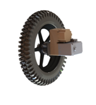
The part numbers of the motors and gearbox on R1 and R2 were BLVM640N-GFS + GFS6G100FR.

The part numbers of the motors and gearbox on the smaller R3 were Maxon EC 90 Flat + GP81A.

Next steps

Now that we know the mechanics of the robot we can start building it. In the next post we will start looking at the electronics and motor controls. While the nature of the blog makes it seem that this design is a serial process, in reality lots of things are happening in parallel. While the mechanical team is designing the chassis, the electrical team is finding the electrical components needed in order for the mechanical person to know what needs mounted.

It is also important to work with the electrical team to figure out wire routing while the chassis is being developed.


Note of the editor: This post has been merged from the posts “Hands On Ground Robot & Drone Design Series” and “Mechanical & Wheels – Hands On Ground Robot Design“.
Intel RealSense 3D Camera for robotics & SLAM (with code)

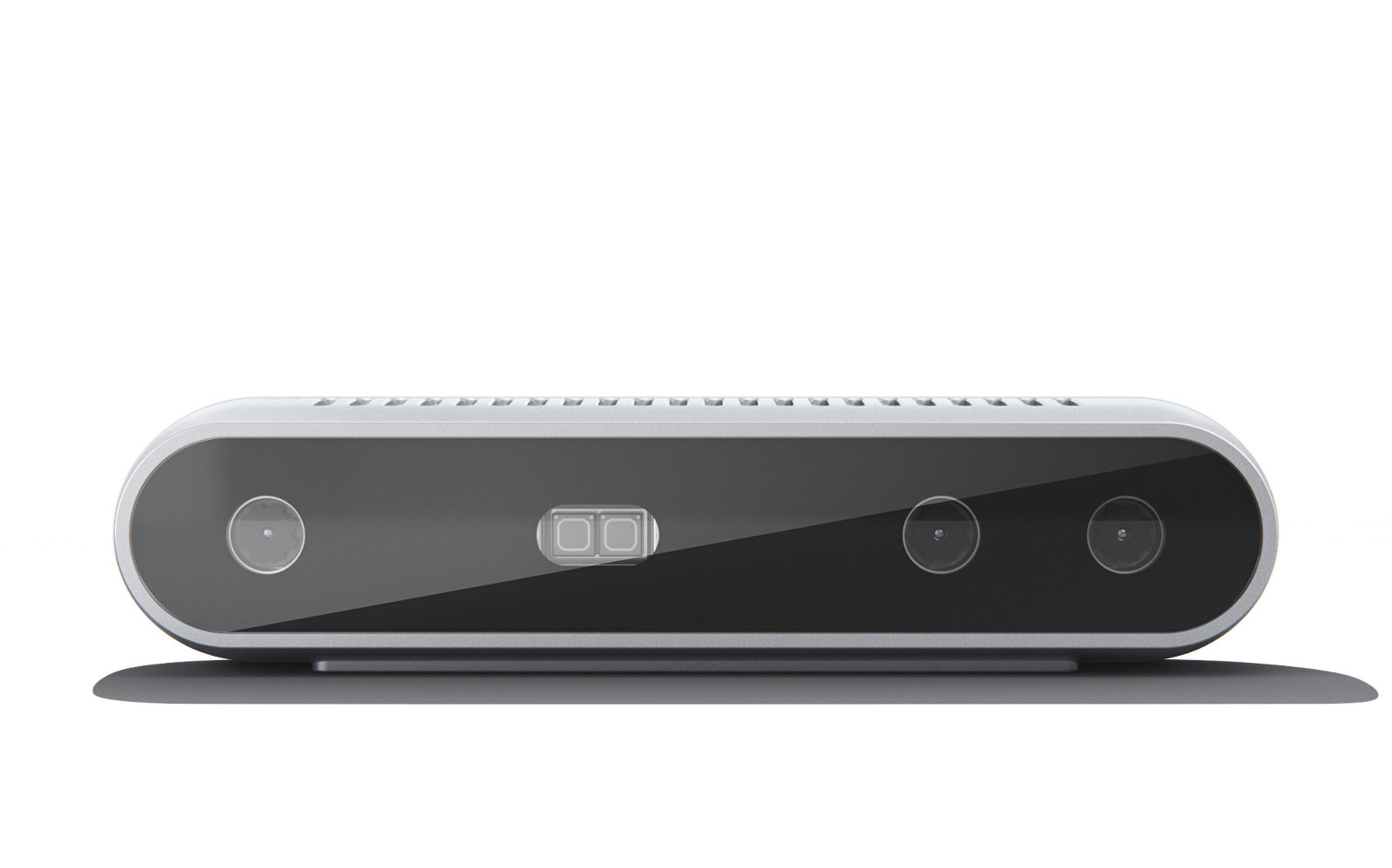
The Intel® RealSense™ D400 Depth Cameras. Credit: Intel Corporation

The Intel RealSense cameras have been gaining in popularity for the past few years for use as a 3D camera and for visual odometry. I had the chance to hear a presentation from Daniel Piro about using the Intel RealSense cameras generally and for SLAM (Simultaneous Localization and Mapping). The following post is based on his talk.

Comparing depth and color RGB images

Depth Camera (D400 series)

Depth information is important since that gives us the information needed to understand shapes, sizes, and distance. This lets us (or a robot) know how far it is from items to avoid running into things and to plan path around obstacles in the image field of view. Traditionally this information has come from RADAR or LIDAR, however in some applications we can also get that from cameras. In cameras we often get depth from using 2 cameras for stereo vision.

The Intel RealSense Depth camera (D400 series) uses stereoscopic depth sensing to determine the range to an item. So essentially it has two cameras and can do triangulation from them for stereo. This sensor uses two infrared cameras for the stereo and then also has an RGB camera onboard. So you can get 4 data products from the sensor; RGB image, depth image, left infrared image, and right infrared image. Think of each image frame as a 3D snapshot of the environment, where each color (RGB) pixel also has a range value (depth) to the item that is in the image. The farther the items are from the camera the greater the range/depth error will be.

Applications In Computer Vision

The D400 cameras have an infrared projector for getting better features on surfaces with minimal texture in the infrared camera for computing the stereo reconstruction. This projector can be turned on and off if you want. Disabling the projector is often useful for tracking applications (since the projected dots don’t move with the items being tracked).

Realsense D400 Cameras Versions

One thing to be aware is that the infrared images are rectified (to make the images look the same in a common plane) in the camera, however the RGB camera image is not rectified. This means that if you want the depth and RGB images to line up well, you need to manually rectify the RGB image.

Pro Tip 1: The driver has a UV map to help map from the depth pixel to the RGB image to help account for the difference in image sizes. This lets you match the depth to RGB image data points better.

Pro Tip 2: If using the D435i (the IMU version), use the timestamps from the images and IMU to synchronize the two sensors. If you use system time (from your computer) there will be more error (partially due to weird USB timing).

Pro Tip 3: The cameras have Depth Presets. These are profiles that let you optimize various settings for various conditions. Such as high density, high accuracy, etc..

Pro Tip 4: Make sure your exposure is set correctly. If you are using auto exposure try changing the Mean Intensity Set Point (the setting is not where exposure is, it is under AE control, not the most obvious).
If you want to use manual exposure you can play with are Exposure setpoint and Gain constant. Start with the exposure setpoint, then adjust the gain.

You might also want to see this whitepaper for more methods of tuning the cameras for better performance.

Visual Odometry & SLAM (T265)

Visual odometry is the generic term for figuring out how far you have moved using a camera. This is as opposed to “standard” odometry using things such as wheel encoders, or inertial odometry with a IMU.

These are not the only ways to get odometry. Having multiple sources of odometry is nice so you can take the advantages of each type and fuse them together (such as with a Kalman filter).

RealSense T265 is a tracking camera that is designed to be more optimal for Visual Odometry and SLAM (wider field of view and not using infrared light). It can do SLAM onboard as well as loop closure. However, this camera is not able to return RGB images (since it does not have a RGB camera onboard) and the depth returned is not as good as the D400 series (and can be a little trickier to get).

Using both a RealSense D435i sensor and a RealSense T265 sensor can provide both the maps and the better quality visual odometry for developing a full SLAM system. The D435i used for the mapping, and the T265 for the tracking.

Software

RealSense Putting Everything Together to Build a Full System

Intel provides the RealSense SDK2.0 library for using the RealSense cameras. It is Open Source and work on Mac, Windows, Linux, and Android. There are also ROS and OpenCV wrappers.

Click here for the developers page with the SDK.

Within the SDK (software development kit) it includes a viewer to let you view images, record images, change settings, or update the firmware.

Pro Tip 5: Spend some time with the viewer looking at the camera and depth images when designing your system so you can compare various mounting angles, heights, etc.. for the cameras.

The RealSense SDK (software development kit) has a few filters that can run on your computer to try and improve the returned depth map. You can play with turning these on and off in the viewer. Some of these include:

  1. Decimation Filter
  2. Spatial Edge-Preserving Filter
  3. Temporal Filter
  4. Holes Filling Filter

Within ROS there is a realsense-ros package that provides a wrapper for working with the cameras in ROS and lets you view images and other data in RVIZ.

ROS RealSense Occupancy Map package is available as an experimental feature in a separate branch of the RealSense git repo. This uses both the D400 and T265 cameras for creating the map.

For SLAM with just the D435i sensor, see here.

Pro Tip 6: You can use multiple T265 sensors for better accuracy. For example, if one sensor is pointed forward and another backwards; you can use the confidence values from each sensor to feed into a filter.

I know this is starting to sound like a sales pitch

Pro Tip 7: If you have multiple cameras you can connect and query for a serial number to know which cameras is which.
Also if you remove the little connector at the top of the camera you can wire and chain multiple cameras together to synchronize them. (This should work in the SDK 2.0)

See this whitepaper for working with multiple camera configurations. https://simplecore.intel.com/realsensehub/wp-content/uploads/sites/63/Multiple_Camera_WhitePaper04.pdf

Pro Tip 8: Infinite depth points (such as points to close or to far from the sensor) have a depth value of 0. This is good to know for filtering.

Here are two code snippet’s for using the cameras provided by Daniel, to share with you. The first one is for basic displaying of images using python. The second code snippet is using OpenCV to also detect blobs, also using python.

## License: Apache 2.0. See LICENSE file in root directory.
## Copyright(c) 2015-2017 Intel Corporation. All Rights Reserved.

###############################################
##      Open CV and Numpy integration        ##
###############################################

import pyrealsense2 as rs
import numpy as np
import cv2


cv2.namedWindow('RealSense', cv2.WINDOW_AUTOSIZE)

# Configure depth and color streams
pipeline = rs.pipeline()
config = rs.config()
config.enable_stream(rs.stream.depth, 640, 480, rs.format.z16, 30)
config.enable_stream(rs.stream.color, 640, 480, rs.format.bgr8, 30)

# Start streaming
pipeline.start(config)

try:
    while True:

        
        # Wait for a coherent pair of frames: depth and color
        frames = pipeline.wait_for_frames()
        depth_frame = frames.get_depth_frame()
        color_frame = frames.get_color_frame()
        if not depth_frame or not color_frame:
            continue

        # Convert images to numpy arrays
        depth_image = np.asanyarray(depth_frame.get_data())
        color_image = np.asanyarray(color_frame.get_data())

        # Apply colormap on depth image (image must be converted to 8-bit per pixel first)
        
        scaled_depth=cv2.convertScaleAbs(depth_image, alpha=0.08)
        depth_colormap = cv2.applyColorMap(scaled_depth, cv2.COLORMAP_JET)

        # Stack both images horizontally
        images = np.hstack((color_image, depth_colormap))

        # Show images
        cv2.imshow('RealSense', images)


        k = cv2.waitKey(1) & 0xFF
        if k == 27:
            break

finally:

    # Stop streaming
    pipeline.stop()
## License: Apache 2.0. See LICENSE file in root directory.
## Copyright(c) 2015-2017 Intel Corporation. All Rights Reserved.

###############################################
##      Open CV and Numpy integration        ##
###############################################

import pyrealsense2 as rs
import numpy as np
import cv2

def nothing(args):
    pass

def detectBlobs(mask):
        # Set up the SimpleBlobdetector with default parameters.
    params = cv2.SimpleBlobDetector_Params()
         
    # Change thresholds
    params.minThreshold = 1;
    params.maxThreshold = 255;
    
    # Filter by Area.
    params.filterByArea = True
    params.maxArea = 4000
    params.minArea = 300
    
    # Filter by Circularity
    params.filterByCircularity = True
    params.minCircularity = 0.1
    
    # Filter by Convexity
    params.filterByConvexity = True
    params.minConvexity = 0.5
    
    # Filter by Inertia
    params.filterByInertia = True
    params.minInertiaRatio = 0.1

         
    detector = cv2.SimpleBlobDetector_create(params)
 
    # Detect blobs.
    reversemask= mask
    keypoints = detector.detect(reversemask)
    im_with_keypoints = cv2.drawKeypoints(mask, keypoints, np.array([]),
            (0,0,255), cv2.DRAW_MATCHES_FLAGS_DRAW_RICH_KEYPOINTS)
    return im_with_keypoints

def thresholdDepth(depth):
    depth[depth==0] = 255 #set all invalid depth pixels to 255
    threshold_value = cv2.getTrackbarPos('Threshold','Truncated Depth')
    # Zero if dist>TH
    ret,truncated_depth=cv2.threshold(scaled_depth,threshold_value,255,cv2.THRESH_BINARY_INV) 
    return truncated_depth

cv2.namedWindow('RealSense', cv2.WINDOW_AUTOSIZE)
cv2.namedWindow('Truncated Depth', cv2.WINDOW_AUTOSIZE)
cv2.createTrackbar('Threshold','Truncated Depth',30,255,nothing)

# Configure depth and color streams
pipeline = rs.pipeline()
config = rs.config()
config.enable_stream(rs.stream.depth, 640, 480, rs.format.z16, 30)
config.enable_stream(rs.stream.color, 640, 480, rs.format.bgr8, 30)

# Start streaming
pipeline.start(config)

try:
    while True:

        
        # Wait for a coherent pair of frames: depth and color
        frames = pipeline.wait_for_frames()
        depth_frame = frames.get_depth_frame()
        color_frame = frames.get_color_frame()
        if not depth_frame or not color_frame:
            continue

        # Convert images to numpy arrays
        depth_image = np.asanyarray(depth_frame.get_data())
        color_image = np.asanyarray(color_frame.get_data())

        # Apply colormap on depth image (image must be converted to 8-bit per pixel first)
        scaled_depth=cv2.convertScaleAbs(depth_image, alpha=0.08)
        depth_colormap = cv2.applyColorMap(scaled_depth, cv2.COLORMAP_JET)

        # Stack both images horizontally
        images = np.hstack((color_image, depth_colormap))

        # Show images
        cv2.imshow('RealSense', images)
        truncated_depth=thresholdDepth(scaled_depth)
        truncated_depth=detectBlobs(truncated_depth)
        cv2.imshow('Truncated Depth', truncated_depth)

        k = cv2.waitKey(1) & 0xFF
        if k == 27:
            break

finally:

    # Stop streaming
    pipeline.stop()

I hope you found this informative and can make use of the Pro Tips.

Thank you to Daniel for presenting this information and allowing me to share it. This content is based on his talk. Daniel has also provided the full slide set that can be accessed by clicking here.

Disclaimer: I have not received any funding or free items from Intel.

Liked this article? Take a second to support me on Patreon! This post appeared first on Robots For Roboticists.

Using hydraulics for robots: Introduction

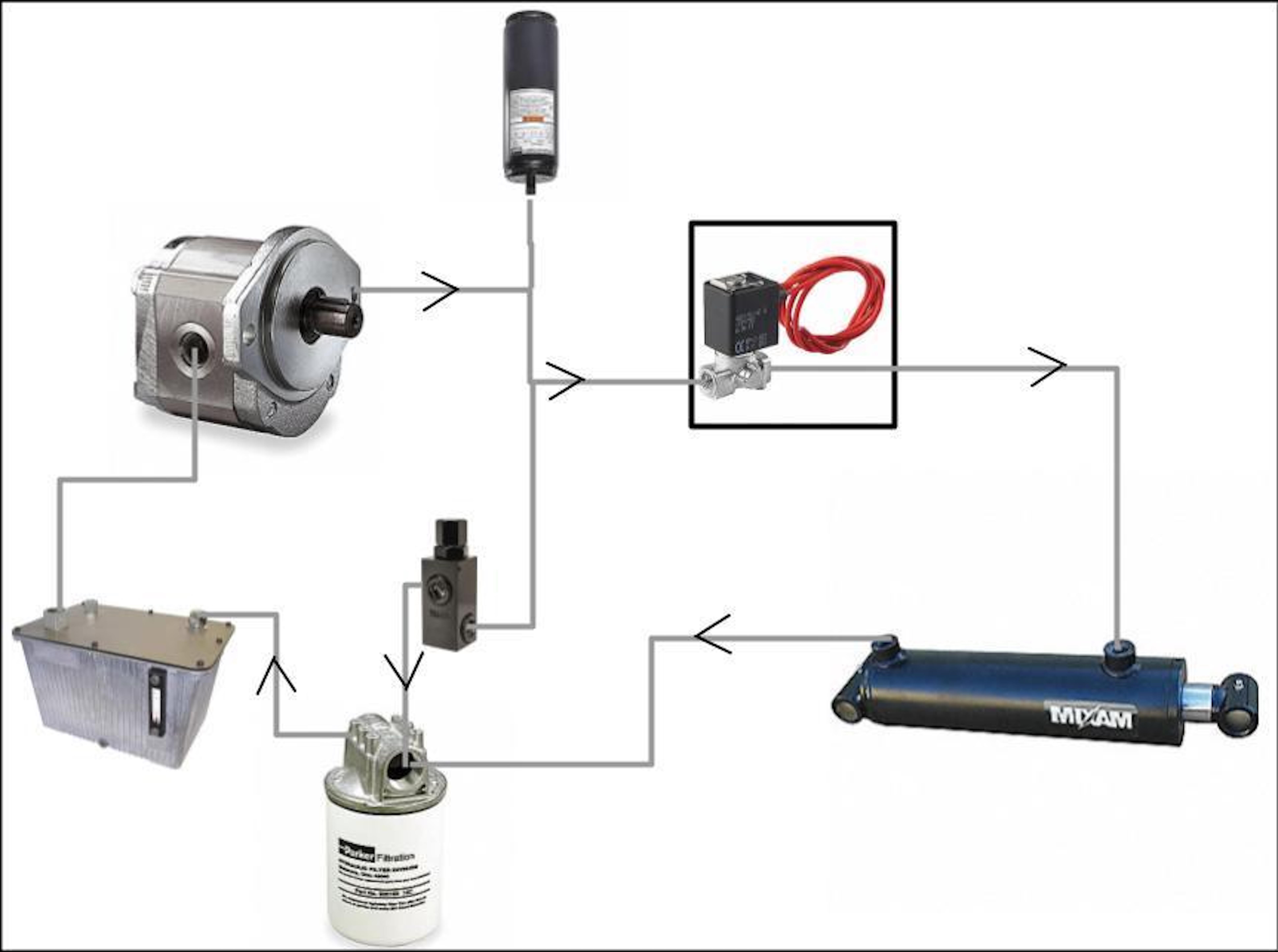
From the Reservoir the fluid goes to the Pump where there are three connections. 1. Accumulator(top) 2. Relief Valve(bottom) & 3. Control Valve. The Control Valve goes to the Cylinder which returns to a filter and then back to the Reservoir.

Hydraulics are sometimes looked at as an alternative to electric motors.

Some of the primary reasons for this include:

  • Linear motion
  • Very high torque applications
  • Small package for a given torque
  • Large number of motors that can share the reservoir/pump can increase volume efficiency
  • You can add dampening for shock absorption

However there are also some downsides to using hydraulics including:

  • More parts are required (however they can be separated from the robot in some applications)
  • Less precise control (unless you use a proportional valve)
  • Hydraulic fluid (mess, leaks, mess, and more mess)

Hydraulic systems use an incompressible liquid (as opposed to pneumatics that use a compressible gas) to transfer force from one place to another. Since the hydraulic system will be a closed system (ignore relief valves for now) when you apply a force to one end of the system that force is transferred to another part of that system. By manipulating the volume of fluid in different parts of the system you can change the forces in different parts of the system (Remember Pascal’s Law from high school??).

So here are some of the basic components used (or needed) to develop a hydraulic system.

Pump

The pump is the heart of your hydraulic system. The pump controls the flow and pressure of the hydraulic fluid in your system that is used for moving the actuators.

The size and speed of the pump determines the flow rate and the load at the actuator determines the pressure. For those familiar with electric motors the pressure in the system is like the voltage, and the flow rate is like the electrical current.

Pump Motor

We know what the pump is, but you need a way to “power” the pump so that it can pump the hydraulic fluid. Generally the way you power the pump is by connecting it to an electric motor or gas/diesel engine.

Hydraulic Fluid

Continuing the analogy where the pump is the heart, the hydraulic fluid is the blood of the system. The fluid is what is used to transfer the pressure from the pump to the motor.

Hydraulic Hoses (and fittings to connect things)

These are the arteries and veins of the system that allows for the transfer of hydraulic fluid.

Hydraulic Actuators – Motor/Cylinder

cylinder
Cylinder [Source]
Motor [Source]

The actuator is generally the reason we are designing this hydraulic system. The motor is essentially the same as the pump; however instead of going from a mechanical input to generating the pressure, the motor converts the pressure into mechanical motion.

Actuators can come in the form of linear motion (referred to as a hydraulic cylinder) or rotary motion motors.

For cylinders, you generally apply a force and the cylinder end extends, and then if you release the force and the cylinder gets pushed back in (think of a car lift). This is the classic and most common use of hydraulics.

For rotary motors there are generally 3 connections on the motor.

  • A – Hydraulic fluid input/output line
  • B – Hydraulic fluid input/output line
  • Drain – Hydraulic fluid output line (generally only on motors, not cylinders)

Depending on the motor you can either only use A as the fluid input and B as the fluid output and the motor only spins in one direction. Or some motors can spin in either direction based on if A or B is used as the input or output of the hydraulic fluid.

The drain line is used so when the system is turned off, the fluid has a way to get out of the motor (to deal with internal leakage and to not blow out seals). In some motors the drain line is connected to one of the A or B lines. Also their are sometimes multiple drain lines so that you can route the hydraulic hoses from different locations.

Note: While the pump and motor are basically the same component. You usually can not switch their role due to how they are designed to handle pressure and the pumps usually not being backdrivable.

There are some actuators that are designed to be leakless and hold the fluid and pressure (using valves) so that the force from the actuator is held even without the pump. For example these are used in things like automobile carrying trucks that need to stack cars for transport.

Reservoir

This is essentially a bucket that holds the fluid. They are usually a little fancier so that they have over pressure relief valves, lids, filters, etc..

The reservoir is also often a place where the hydraulic fluid can cool down if it is getting hot within the system. As the fluid gets hotter it can get thinner which can result in increased wear of your motor and pump.

Filter

Keeps your hydraulic fluid clean before going back to the reservoir. Kind of like a persons kidneys.

Valves (and Solenoids)

solenoid valve
Valve (metal) with Solenoid (black) attached on top [Source]

Valves are things that open and close to allow the control of fluid. These can be controlled by hand (ie. manual), or more often my some other means.

One common method is to use a solenoid which is a device that when you apply a voltage can be used to open a valve. Some solenoids are latching, which means you quickly apply a voltage and it opens the valves, and then you apply a voltage again (usually switching polarity) to close the valve.

There are many types of valves, I will detail a few below.

Check Valves (One Way Valve)

These are a type of valve that can be inline to allow the flow of hydraulic fluid in only one direction.

Relief Valve

These are a type of valve that automatically opens (And lets fluid out) when the pressure gets to high. This is a safety feature so you don’t damage other components and/or cause an explosion.

Pilot Valve

These are another special class of valve that can use a small pressure to control a much larger pressure valve.

Pressure & Flow-rate Sensors/Gauges 

You need to have sensors (with a gauge or computer output) to measure the pressure and/or flow-rate so you know how the system is operating and if it is operating how you expect it to operate.

Accumulator

The accumulator is essentially just a tank that holds fluid under pressure that has its own pressure source. This is used to help smooth out the pressure and take any sudden loads from the motor by having this pressure reserve. This is almost like how capacitors are used in electrical power circuits.

The pressure source in the accumulator is often a weight, springs, or a gas.

There will often be a check valve to make sure the fluid in the accumulator does not go back to the pump.


I am not an expert on hydraulic systems. But I hope this quick introduction helps people. Liked it? Take a second to support me on Patreon!

Underwater robot photography and videography


I had somebody ask me questions this week about underwater photography and videography with robots (well, now it is a few weeks ago…). I am not an expert at underwater robotics, however as a SCUBA diver I have some experience that can be applicable towards robotics.

Underwater Considerations

There are some challenges that exist with underwater photography and videography, that are less challenging above the water. Some of them include:

1) Water reflects some of the light that hits the surface, and absorbs the light that travels through it. This causes certain colors to not be visible at certain depths. If you need to see those colors you often need to bring strong lights to restore the visibility of those wavelengths that were absorbed. Red’s tend to disappear first, blues are the primary color seen as camera depth increases. A trick that people often try is to use filters on the camera lens to make certain colors more visible.

If you are using lights then you can get the true color of the target. Sometimes if you are taking images you will see one color with your eye, and then when the strobe flashes a “different color” gets captured. In general you want to get close to the target to minimize the light absorbed by the water.

Visible colors at given depths underwater. [Image Source]

For shallow water work you can often adjust the white balance to sort of compensate for the missing colors. White balance goes a long ways for video and compressed images (such as .jpg). Onboard white balance adjustments are not as important for photographs stored as with a raw image format, since you can deal with it in post processing. Having a white or grey card in the camera field of view (possibly permanently mounted on the robot) is useful for setting the white balance and can make a big difference. The white balance should be readjusted every so often as depth changes, particularly if you are using natural lighting (ie the sun).

Cold temperate water tends to look green (such as a freshwater quarry) (I think from plankton, algae, etc..). Tropical waters (such as in the Caribbean) tend to look blue near the shore and darker blue as you get further away from land (I think based on how light reflects off from the bottom of the water)… Using artificial light sources (such as strobes) can minimize those colors in your imagery.

Auto focus generally works fine underwater. However if you are in the dark you might need to keep a focus light turned on to help the autofocus work, and then a separate strobe flash for taking the image. Some systems turn the focus light off when the images are being taken. This is generally not needed for video as the lights are continuously turned on.

2) Objects underwater appear closer and larger than they really are. A rule of thumb is that the objects will appear 25% larger and/or closer.

3) Suspended particles in the water (algae, dirt, etc..) scatters light which can make visibility poor. This can obscure details in the camera image or make things look blurry (like the camera is out of focus). A rule of thumb is your target should be less than 1/4 distance away from the camera as your total visibility.

The measure of the visibility is called turbidity. You can get turbidity sensors that might let you do something smart (I need to think about this more).

To minimize the backscatter from turbidity there is not a “one size fits all” solution. The key to minimizing backscatter is to control how light strikes the particles. For example if you are using two lights (angled at the left and right of the target), the edge of each cone of light should meet at the target. This way the water between the camera and the target is not illuminated. For wide-angle lenses you often want the light to be behind the camera (out of its plane) and to the sides at 45° angles to the target. With macro lenses you usually want the lights close to the lens.

“If you have a wide-angle lens you probably will use a domed port to protect the camera from water and get the full field of view of the camera.
The dome however can cause distortion in the corners. Here is an interesting article on flat vs dome ports.”

Another tip is to increase the exposure time (such as 1/50th of a second) to allow more natural light in, and use less strobe light to reduce the effect from backscatter.

4) Being underwater usually means you need to seal the camera from water, salts, (and maybe sharks). Make sure the enclosure and seals can withstand the pressure from the depth the robot will be at. Also remember to clean (and lubricate) the O rings in the housing.

“Pro Tip:Here are some common reasons for O ring seals leaking:
a. Old or damaged O rings. Remember O rings don’t last forever and need to be changed.
b. Using the wrong O ring
c. Hair, lint, or dirt getting on the O ring
d. Using no lubricant on the O ring
e. Using too much lubricant on the O rings. (Remember on most systems the lubricant is for small imperfections in the O ring and to help slide the O rings in and out of position.)”

5) On land it is often easy to hold a steady position. Underwater it is harder to hold the camera stable with minimal motion. If the camera is moving a faster shutter speed might be needed to avoid motion blur. This also means that less light is entering the camera, which is the downside of having the faster shutter speed.

When (not if) your camera floods

When your enclosure floods while underwater (or a water sensor alert is triggered):

a. Shut the camera power off as soon as you can.
b. Check if water is actually in the camera. Sometimes humidity can trigger moisture sensors. If it is humidity, you can add desiccant packets in the camera housing.
c. If there is water, try to take the camera apart as much as you reasonably can and let it dry. After drying you can try to turn the camera on and hope that it works. If it works then you are lucky, however remember there can be residual corrosion that causes the camera to fail in the future. Water damage can happen instantaneously or over time.
d. Verify that the enclosure/seals are good before sending the camera back in to the water. It is often good to do a leak test in a sink or pool before going into larger bodies of water.
e. The above items are a standard response to a flooded camera. You should read the owner’s manual of your camera and follow those instructions. (This should be obvious, I am not sure why I am writing this).


Do you have other advice for using cameras underwater and/or attached to a robot? Leave them in the comment section below.


I want to thank John Anderson for some advice for writing this post. Any mistakes that may be in the article are mine and not his.

The main image is from divephotoguide.com. They have a lot of information on underwater cameras, lens, lights and more.

This post appeared first on Robots For Roboticists.

Battery safety and fire handling

Lithium battery safety is an important issue as there are more and more reports of fires and explosions. Fires have been reported in everything from cell phones to airplanes to robots.

If you don’t know why we need to discuss this, or even if you do know, watch this clip or click here.

I am not a fire expert. This post is based on things I have heard and some basic research. Contact your local fire department for advice specific to your situation. I had very little success contacting my local fire department about this, hopefully you will have more luck.

Preventing Problems

1. Use a proper charger for your battery type and voltage. This will help prevent overcharging. In many cases lithium-ion batteries catch fire when the chargers keep dumping charge into the batteries after the maximum voltage has been reached.

2. Use a battery management system (BMS) when building battery packs with multiple cells. A BMS will monitor the voltage of each cell and halt charging when any cell reaches the maximum voltage. Cheap BMS’s will stop all charging when any cell reaches that maximum voltage. Fancier/better BMS’s can individually charge each cell to help keep the battery pack balanced. A balanced pack is good since each cell will be a similar voltage for optimal battery pack performance. The fancy BMS’s can also often detect if a single cell is reading wrong. There have been cases of a BMS’s working properly but a single cell going bad which confuses the BMS; and yields a fire/explosion.

3. Only charge batteries in designated areas. A designated area should be non combustible. For example cement, sand, cinder block and metal boxes are not uncommon to use for charging areas. For smaller cells you can purchase fire containment bags designed to put the charging battery in.
lipo lithiom ion battery charging bag

In addition the area where you charge the batteries should have good ventilation.

I have heard that on the Boeing Dreamliner, part of the solve for their batteries catching fire on planes, was to make sure that the metal enclosure that the batteries were in could withstand the heat of a battery fire. And also to make sure that in the event of a fire the fumes would vent outside the aircraft and not into the cabin.

Dreamliner airline battery fire

Dreamliner battery pack before and after fire. [SOURCE]

4. Avoid short circuiting the batteries. This can cause a thermal runoff which will also cause a fire/explosion. When I say avoid short circuiting the battery you are probably thinking of just touching the positive and negative leads together. While that is an example you need to think of other methods as well. For example puncturing a cell (such as with a drill bit or a screw driver) or compressing the cells, can cause a short-circuit with a resulting thermal runoff.

5. Don’t leave batteries unattended when charging. This will let people be available in case of a problem. However, as you saw in the video above, you might want to keep a distance from the battery in case there is a catastrophic event with flames shooting out from the battery pack.

6. Store batteries within the specs of the battery. Usually that means room temperature and out of direct sunlight (to avoid overheating).

7. Training of personnel for handling batteries, charging batteries, and what to do in the event of a fire. Having people trained in what to do can be important so that they stay safe. For example, without training people might not realize how bad the fumes are. Also make sure people know where the fire pull stations are and where the extinguishers are.

Handling Fires

1. There are 2 primary issues with a lithium fire. The fire itself and the gases released. This means that even if you think you can safely extinguish the fire, you need to keep in mind the fumes and possibly clear away from the fire.

2a. Lithium batteries which are usually in the form of small non-rechargeable batteries (such as in a watch) in theory require a class D fire extinguisher. However most people do not have one available. As such, for the most part you need to just let it burn itself out (it is good that the batteries are usually small). You can use a standard class ABC fire extinguisher to prevent the spread of the fire. Avoid using water on the lithium battery itself since the lithium and water can react violently.

2b. Lithium-ion batteries (including LiFePO4) that are used on many robots, are often larger and rechargeable. For these batteries there is not a lot of actual lithium metal in the battery, so you can use water or a class ABC fire extinguisher. You do not use a class D extinguisher with these batteries.

With both of these types of fires, there is a good chance that you will not be able to extinguish the it. If you can safety be in the area your primary goal is to allow the battery to burn in a controlled and safe manner. If possible try to get the battery outside and on a surface that is not combustible. As a reminder lithium-ion fires are very hot and flames can shoot out from various places unexpectedly; you need to be careful and only do what you can do safety. If you have a battery with multiple cells it is not uncommon for each cell to catch fire separately. So you might see the flames die down, then shortly after another cell catches fire, and then another; as the cells cascade and catch fire.

PASS fire extinguisher

A quick reminder about how to use a fire extinguisher. Remember first you Pull the pin, then you Aim at the base of the fire, then you Squeeze the handle, followed by Sweeping back and forth at the base of the fire. [SOURCE]

3. In many cases the batteries are in an enclosure where if you spray the robots with an extinguisher you will not even reach the batteries. In this case your priority is your safety (from fire and fumes), followed by preventing the fire from spreading. To prevent the fire from spreading you need to make sure all combustible material is away from the robot. If possible get the battery pack outside.

In firefighting school a common question is: Who is the most important person? To which the response is, me!

4. If charging the battery, try to unplug the battery charger from wall. Again only if you can do this safely.


I hope you found the above useful. I am not an expert on lithium batteries or fire safety. Consult with your local experts and fire authorities. I am writing this post due to the lack of information in the robotics community about battery safety.

As said by Wired “you know what they say: With great power comes great responsibility.”.


Thank you Jeff (I think he said I should call him Merlin) for some help with this topic.

National Robot Safety Conference 2017

I had the opportunity to attend the National Robot Safety Conference for Industrial Robots today in Pittsburgh, PA (USA). Today was the first day of a three-day conference. While I mostly cover technical content on this site; I felt that this was an important conference to attend since safety and safety standards are becoming more and more important in robot system design. This conference focused specifically on industrial robots. That means the standards discussed were not directly related to self-driving cars, personal robotics, or space robots (you still don’t want to crash into a martian and start an inter-galactic war).

In this post I will go into a bit of detail on the presentations from the first day. Part of the reason I wanted to attend the first day was to hear the overview and introductory talks that formed a base for the rest of the sessions.

The day started out with some Standards Bingo. Lucky for us the conference organizers provided a list of standards terms, abbreviations, codes, and titles (see link below). For somebody (like myself) who does not work with industrial robot safety standards every day, when people start rattling off safety standard numbers it can get confusing very fast.

Quick, what is ISO 10218-1:2011 or IEC 60204-1:2016? For those who do not know, (me included) those are Safety requirements for industrial robots — Part 1: Robots and Safety of machinery – electrical equipment — Part 1: General requirements.

Click here for a post with a guide to relevant safety standards, Abbreviations, Codes & Titles.

The next talk was from Carla Silver at Merck & Company Inc. she introduced what safety team members need to remember to be successful, and introduced Carla’s Top Five List.

  1. Do not assume you know everything about the safety of a piece of equipment!
  2. Do not assume that the Equipment Vendor has provided all the information or understands the hazards of the equipment.
  3. Do not assume that the vendor has built and installed the equipment to meet all safety regulations.
  4. Be a “Part of the Process”. – Make sure to involve the entire team (including health and safety people)
  5. Continuous Education

I think those 5 items are a good list for life in general.

The prior talk set the stage for why safety can be tricky and the amount of work it takes to stay up to date.

Robot integrator is a certification (and way to make money) from Robotic Industries Association (RIA) that helps provide people who come trained to fill the safety role while integrating and designing new robot systems.

According to Bob Doyle the RIA Director of Communications, RIA certified robot integrators must understand current industry safety standards and undergo an on-site audit in order to get certified. Every two years they need to recertify. Part of the recertification is having an RIA auditor perform a site visit. When recertifing the integrators are expected to know the current standards. I was happy to hear about the two-year recertification, due to how much changes with robotics technology over two years.

A bit unrelated but A3 is the umbrella association for Robotic Industries Association (RIA) as well as Advancing Vision & Imaging (AIA), and Motion Control & Motor Association (MCMA). Bob mentioned that the AIA and MCMA certifications are standalone from the RIA Certified Integrators. However they are both growing as a way to train industrial engineers for those applications. Both the AIA and MCMA certifications are vendor agnostic for the technology used. There are currently several hundred people with the AIA certification. The MCMA certification was just released earlier this year and has several dozen people certified. Bob said that there are several companies that now require at least one team member on a project to have the above certifications.

The next talk really started to get into the details about Robot System Integrators and Best Practices. In particular risk assessments. Risk assessments is a relatively new part of the integration process, but has a strong focus in the current program. Risk assessments are important due to the number of potential safety hazards and the different types or interactions a user might have with the robot system. The risk assessment helps guide the design as well as how users should interact with the robot . The responsibility to perform this risk assessment is with the robot integrator and not directly with the manufacturer or end-user.

One thing that I heard that surprised me was that many integrators do not share the risk assessment with the end-user since it is considered proprietary to that integrator. However one participant said that you can often get them to discuss it in a meeting or over the phone, just they will not hand over the documents.

After a small coffee break we moved on to discussing some of the regulations in detail. In particular R15.06 which is for Industrial Robot Safety standards, the proposed R15.08 standards for industrial mobile robot safety standards, and the R15.606 collaborative robot safety standards. Here are a few notes that I took:

Types of Standards

  • A – Basic concepts — Ex. Guidance to assess risk
  • B – Generic safety standards — Ex. Safety distances, interlocks, etc..
  • C – Machine specific — ex. From the vendor for a particular robot.

Type C standards overrule type A & B standards.

Parts of a Standard

  • Normative – These are required and often use the language of “shall”
  • Informative – These are recommended or advice and use the language of “should” or “can”. Notes in standards are considered Informative

Key Terms for Safety Standards

  • Industrial Robot – Robot manipulator of at least 3 DOF and its controller
  • Robot System – The industrial robot with its end effector, work piece and periphery equipment (such as conveyor).
  • Robot Cell – Robot system with the safe guarded spaces to include the physical barriers.
robot work cell

Case study that was presented of a 3 robot system in a single cell, and how it was designed to meet safety standards.

R15.06 is all about “keeping people safe by keeping them away from the robot system”. This obviously does not work for mobile robots that move around people and collaborative robots. For that the proposed R15.08 standard for mobile robots and the R15.606 standard for collaborative robots are needed.

R15.08 which is expected to be ratified as a standard in 2019 looks at things like mobile robots, manipulators on mobile robots, and manipulators working while the mobile base is also working. Among other things, the current standard draft says that if an obstacle is detected, the primary mode is for the robot to stop; however dynamic replanning will be allowed.

For R15.606 they are trying to get rid of the term collaborative robot (a robot designed for direct interaction with a human) and think about systems in regard to its application. For example :

…a robotic application where an operator may interact directly with a robot system without relying on perimeter safeguards for protection in pre-determined,low risk tasks…

collaborative robots

After all the talk about standards we spent a bit of time looking at various case studies that were very illuminating for designing industrial robotic systems, and some of the problems that can occur.

One thing unrelated, but funny since this was a safety conference, was a person sitting near the back of the room who pulled a roll of packing tape out of their backpack to tape over their laptop power cable that ran across the floor.

I hope you found this interesting. This was the 29th annual national robot safety meeting (really, I did not realize we had been using robots in industry for that long). If you want to find out more about safety and how it affects your work and robots make sure to attend next year.


I would like to thank RIA for giving me a media pass to attend this event.

Antenna separation: How close can you go?

robot_device-676x507

When building a new robot mechanical engineers always ask me: how close can different antennas be to one another? It is not uncommon to try squeezing 5+ antennas on a single robot (GPS, GPS2 for heading, RTK, joystick, e-stop, communications, etc..). So what is the proper response? The real answer is that it depends heavily on the environment. However, below are the rules of thumb I have learned and have been passed down to me for antenna separation. I do want to give a disclaimer some of this has been passed down as rules of thumb and may not be 100% correct.

Here is the rule: The horizontal distance between antennas should be greater than 1/4 of its wavelength (absolute minimum separation), but it should not be located at the exact multiples of its wavelength (maybe avoid the first 3-4 multiples). If multiple frequency antennas are near each other, then use the spacing distance of the lower frequency antenna, or even better, try to satisfy the rule for both frequencies.

Device Frequency Wavelength 1/4 Wavelength
WiFi 802.11 5.8GHz 5.17cm 1.29cm
WiFi 802.11 2.4GHz 12.49cm 3.12cm
GPS* 1.227GHz 24.43cm 6.11cm
Radios 900MHz 33.3cm 8.33cm

Here is a nice wavelength calculator I just found to generate the table above.

* If you are using two GPS antennas to compute heading then this does not apply. These numbers are strictly for RF considerations.

So, for example, if you have a GPS antenna and a WiFi 2.4GHz antenna you would want them to be separated by at least (more is better, within reason) 8.33cm. And you should avoid putting them at exactly 24.43cm or 33.3cm from each other.

This rule seems to work with the low power antennas that we typically use in most robotics applications. I am not sure how this would work with high power transmitters. For higher power transmitting antennas, you might want greater separation. The power drops off pretty quickly with distance (proportional to the square of the distance).

I also try to separate receive and transmit antennas (as a precaution) to try and prevent interference problems.

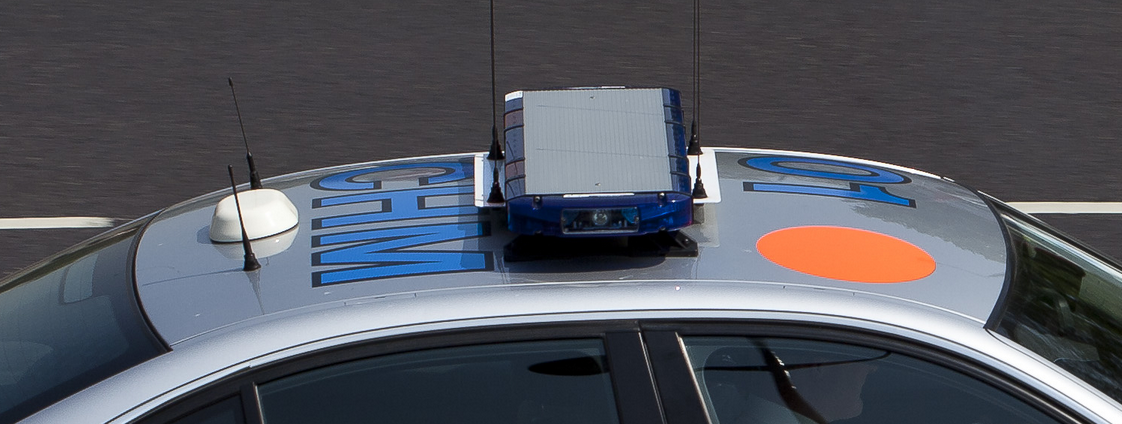
An extension of the above rule is ground planes. Ground planes are conductive reference planes that are put below antennas to reflect the waves to create a predictable wave pattern and can also help prevent multipath waves (that are bouncing off the ground, water, buildings, etc…). The further an antenna is from the ground (since the ground can act as a ground plane), the more likely having a ground place becomes necessary. In its simplest form, a ground plane is a piece of metal that extends out from the antennas base at least 1/4 wavelength in each direction. Fancy ground planes might just be several metal prongs that stick out. A very common ground plane is the metal roof of a vehicle/robot.

Note: Do not confuse ground planes with RF grounds, signal grounds, DC grounds, etc…

Aerial roof markings on London police car. Source: Wikimedia Commons

An example of building a ground plane can be with a GPS antenna. It should be mounted in the center of a metal roofed robot/car or on the largest flat metal location. This will minimize the multipath signals from the ground. If there is no flat metal surface to mount the antenna you can create a ground plane by putting a 12.22cm diameter metal sheet directly below the antenna (about 1/2 the signals wavelength, which gives 1/4 wavelength per side).

Note: Some fancy antennas do not require that you add a ground plane. For example, the Novatel GPS antennas do NOT require you to add a ground plane, as described above.

Other things to watch out for are shadowing between the antennas and sensors and the fresnel zone. For more information on the fresnel zone, and why antennas are not actually just line of site, click here.

Book Review: ‘Peer Reviews in Software, A Practical Guide,’ by Karl Wiegers

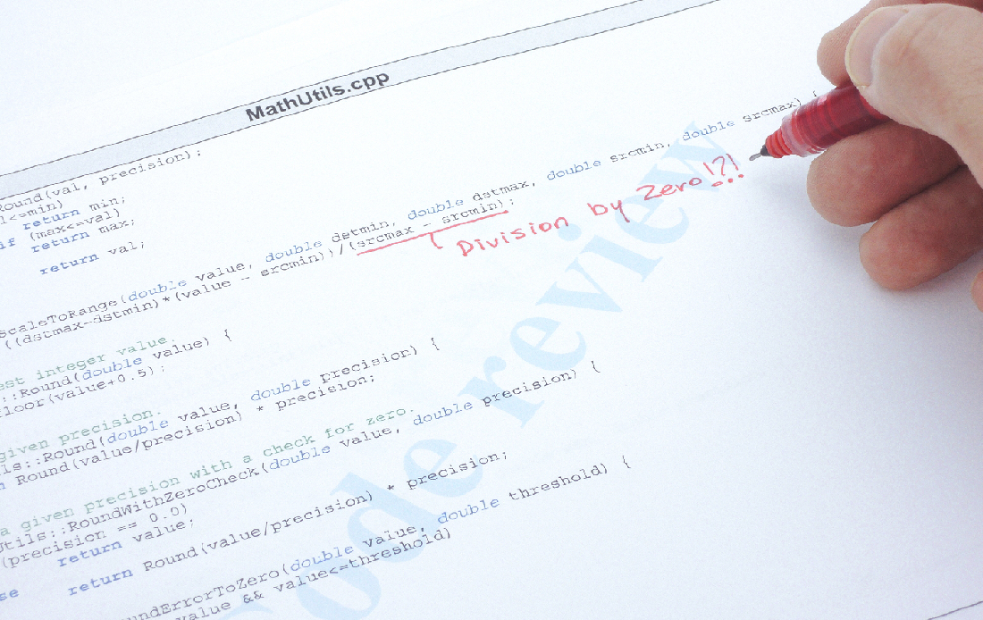
Code review of a C++ program with an error found.

I have been part of many software teams where we desired to do code reviews. In most of those cases the code reviews did not take place, or were pointless and a waste of time. So the question is: how do you effectively conduct peer reviews in order to improve the quality of your systems?

I found this book, Peer Reviews in Software: A Practical Guide by Karl E. Wiegers. This book was recommended to me, and having “practical guide” in the title caught my attention —  I have reviewed other books that claimed practical, but were not. Hopefully this book will help provide me (and you) with tools for conducting valuable code reviews.

Peer Reviews in Software: A Practical Guide. Photo: Amazon

As a human, I will make mistakes when programming; finding my mistakes is often difficult since I am very close to my work. How many times have you spent hours trying to find a bug in your code only to realize you had a bad semi-colon or parentheses? Another person who has not worked on the code for hours might have been able to spot the problem right away. When I first started programming it could be embarrassing to have somebody review my code and point out the problems. However now that I am more senior, I do not view it as an embarrassment, but as a learning opportunity since everybody has a different set of experiences that influences their code. I would encourage other developers to view it as a learning experience and not be bashful about reviews. Remember the person is critiquing the work, not you; this is how to become a better developer.

According to Wiegers, there are many types of peer reviews including: inspections, team reviews, walkthroughs, pair programming, peer desk check passaround, and finally ad hoc review.

This book is divided into three sections:

  1. Cultural & social aspects
  2. Different types of reviews (with a strong focus on inspection)
  3. How to implement review process within your projects

Cultural & Social Aspects

In this first section of the book, the author makes the argument that quality work is not free and that “paying” the extra cost of peer reviews is a good investment in the future. By having peer review you can reduce failures before the product is released out into the world and any applicable reworks. Shifting the defect detection to the early stages of a product has huge potential payoff, due to high costs of fixing defects found late in the release cycle, or after release. The space shuttle program found the relative cost for fixing a defect is: $1, if found during initial inspection; $13, if found during a system test; and $92, to fix after delivery! In the book, the author documents various companies who saved substantial amounts of time and money all by having code inspection programs.

One thing I like is the reference to IEEE 1999, which talks about other items that are good to review. People don’t think about it but other things, such as marketing brochures, requirement specifications, user guides, test plans and many other things, are good candidates for peer review.

I have seen many project teams try to do error tracking and/or code reviews but fail, due to team culture. I saw one case where peer review actually worked: when a dedicated person’s only job was to manage reliability in the project. He was great at hounding people to track bugs and review code. This book discussed how team culture must be developed to value “quality”. If you are the type of person that does not want to waste time reviewing another’s code, you must remember you will want the other person to “waste” time looking at your code. In this manner, we must all learn to scratch each other’s back. There are also two traps to watch out for:

  1. Becoming lazy and submitting bad code for review since somebody else will find/fix it, or
  2. Trying to perfect your code before sharing it, in order to protect your ego from getting bruised, and to only show your best work.

We also cannot forget managers. Managers need to value quality and provide time and resources for employees to develop good practices. Managers need to understand the point of these exercises are to find flaws and people should not be punished based on those flaws. I have often seen managers not putting time in the schedule for good code reviews.

Types of reviews

Before discussing the types of reviews there is a good discussion on the guiding principles for reviews. Some of the principles are:

  • Check your egos at the door
  • Keep the review team small
  • Find problems during review, but don’t try to fix them at the review. Give up to 1 minute for discussion of fixes.
  • Limit review meeting to 2 hours max
  • Require advanced preparation

There are several types of peer reviews discussed in this book. This list starts with the least formal approach and develops until the most formal approach (the book uses the opposite order which I found non intuitive).

  1. Ad Hoc – These are the spur of the moment meetings where you call a coworker to your desk to help with a small problem. Usually, this just solves an immediate problem. (This is super useful when trying to work out various coordinate transforms)
  2. Peer passaround/deskcheck, – In this approach a copy of the work is sent to multiple reviewers, after which you can then collate all of the reviews. This allows multiple people to look at the code/item and also lets you get something if one person does not respond. In the peer deskcheck version, only one person looks at it instead of passing it around for multiple reviews.
  3. Pair Programming – This is the idea that two people program together. So while there is no official review two sets of eyes see each line of code being typed. This has an added bonus that now two people will understand the code. The downside is that often one of the coders can “doze-off” and not be effective at watching for flaws. Also, many coders might not like this.
  4. Walkthrough – This is where the author of the code walks through the code to a group of reviewers. This is often unstructured and heavily dependent on how good of a job the author prepared. In my experience this is good for helping people understand the code and finding large logic flaws, but not so much for finding smalls flaws/bugs.
  5. Team Review – This is similar to the walkthrough however reviewers are provided with documentation/code in advance to review and their results are collated.
  6. Inspection – Finally, we have the most formal approach which the author appears to favor. In this approach the author of the code does not lead the review, rather, a moderator, often with the help of checklists, will lead the meeting and read out the various sections. After the moderator reads a section, the reviewers discuss it. The author of the code can answer questions and learn how to improve various sections. Often the author might identify other instances of the same problem that the reviewers did not point out. An issue log should be maintained as a formal way of providing feedback and a list to verify fixes against.
Suggested review methods from "Peer Reviews in Software"
Suggested review methods from “Peer Reviews in Software”

The book then spends the next few chapters detailing the inspection method of peer review. Here are just a few notes. As always, read the book to find out more.

  • In most situation 3-7 is a good size group for the inspection. The number of people can be based on the item being reviewed.
  • The review needs to be planned in advance and have time to prepare content to distribute to reviewers.
  • After the meeting the author should address each item in the issue log that was created and submit it to the moderator (or other such person) to verify that the solutions are good.
  • Perform an inspection when that module is ready to pass to the next development stage. Waiting too long can leave a person with a lot of bad code that is now too hard to fix.
  • You can (sort of) measure the ROI by looking at the bugs found and how long they took to find. There are many other metrics detailed in the book.
  • Keep spelling and grammar mistakes on a separate paper and not on the main issue list.

How to implement review processes within your projects

Getting a software team and management to change can be difficult. The last part of this book is dedicated to how you can get reviews started, and how to let them naturally grow within the company. One significant thing identified is to have a key senior person act as a coordinator for building a culture of peer review and to provide training to developers. There is a nice long table in the book of the various pitfalls that an organization may encounter and how to deal with them.

This book also discusses special challenges and how it can affect your review process. Some of the situations addressed are:

  • Large work products
  • Geographic or time separation
  • Distributed reviewers
  • Asynchronous review
  • Generated and non-procedural code
  • To many participants
  • No qualified reviewers available

At the end of this book, there is a link to supplemental material online. I was excited to see this. However when I went to the site, I saw it was all for sale and not free (most things were around $5). That kind of burst my bubble of excitement for the supplemental material. There is a second website for the book that is referenced but does not seem to be valid anymore.

Throughout the book the idea is getting proper training for people on how to conduct inspection reviews. Towards the end of the book, the idea of hiring the book’s author as a trainer to help with this training is suggested.

Overall, I think this is a good book. It introduces people on how to do software reviews. The use of graphics and tables in the book are pretty good. It is practical and easy to read. I also like how this book addresses management and makes the business case for peer reviews. I give this book 4.5 out of 5 stars. The missing 0.5 stars is due to the supplemental material not being free and for not providing those forms with the book.

Disclaimer: I do not know the book author. I purchased this book myself from Amazon.